
Quick Answer
Bring several inputs to an inverting amplifier's summing node through their own resistors and each contributes independently, weighted by its resistor. Split the network into two halves instead, one on each input, and the circuit amplifies the difference between two signals while ignoring what they have in common.
Intuition
Two pans on the same beam
A balance scale does two things at once, and they are worth separating.
Pile several weights into one pan and the pan does not care which is which. Their effect on the beam is the sum, and adding a fourth weight changes nothing about what the first three were doing. That is addition, and it works because the pan has no memory and no opinion.
Load both pans and the beam responds only to the difference. A hundred grams in each and the beam sits level; a hundred and one against a hundred and it tips, by the same amount as one gram against nothing. The scale is blind to what the two pans share and sensitive only to how they differ.
Both of those are op-amp circuits, and they are close relatives. The first is an inverting amplifier with more than one input resistor, and it is almost embarrassingly easy. The second splits the same network across both inputs, and everything hard about it comes from one requirement: the two sides of the beam have to match.
Practitioner
Three currents into a node that does not move
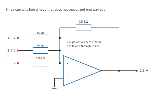
Four junction dots, three of them on the summing column where the inputs arrive.
The previous lesson established that the inverting input sits at a virtual ground: at zero volts, held there by the feedback, and taking no current worth counting. Everything about the summing amplifier follows from that one fact.
Connect a second input resistor to the same node. Its current is set by its own voltage and its own resistance, because the far end of it is at zero. It does not know the first resistor exists.
Worked example — Adding three signals
An invented network: 15 kΩ of feedback, with 1.0 V arriving through 15 kΩ, 2.0 V through 30 kΩ and 5.0 V through 150 kΩ.
The three currents are 66.7 µA, 66.7 µA and 33.3 µA, which add to 167 µA at the node.
All of it leaves through the feedback resistor, putting the output at -2.5 V.
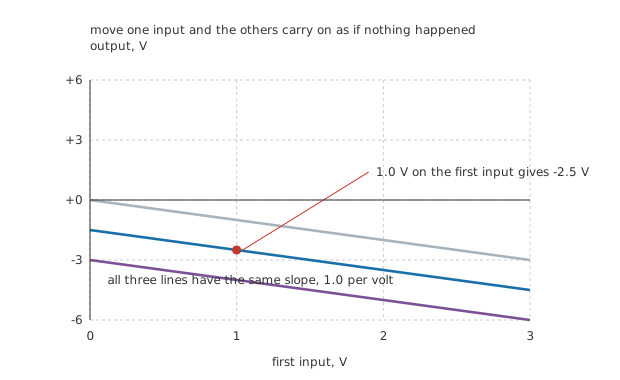
Same slope everywhere. Changing the other channels moves the line without tilting it.
That independence is the whole reason the circuit is worth having. In the figure the first input is swept three times, with the other two channels at zero, at the lesson's settings, and at double them. The three lines are parallel: the other channels shift the output up or down and do not change how the first one behaves.
Try the same thing with three resistors meeting at an ordinary node and it fails immediately, because each source then sees the others through the network and every setting interacts with every other. The virtual ground is what removes the interaction, and it removes it completely.
Engineer
Weights, and where they come from
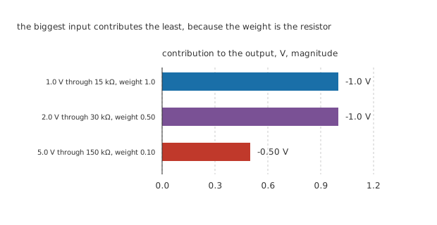
One scale through zero, so the lengths are the contributions.
Each input arrives with a weight, and the weight is the feedback resistor divided by that input's own resistor.
Worked example — What each channel is worth
15 kΩ against 15 kΩ gives a weight of 1.0, so 1.0 V contributes -1.0 V.
30 kΩ gives 0.50, so 2.0 V contributes -1.0 V from twice the voltage.
150 kΩ gives 0.10, so the largest input contributes the smallest amount: -0.50 V.
The weights are what makes the circuit useful rather than merely tidy. An audio mixer sets them with potentiometers so the operator can move them. A control loop uses them to combine a measurement with a setpoint. A converter built out of switched resistors uses binary weights, so each bit contributes half of what the one above it does, and the summing node turns a pattern of switches into a voltage. That last one gets a lesson of its own later in this department.
Two practical points before the difference amplifier.
The feedback resistor sets the overall level and the input resistors set the ratios. Change the feedback resistor and every channel changes together; change one input resistor and only that channel moves. That is the right way round for adjusting a design.
Each source sees only its own resistor. The input resistance presented to channel one is 15 kΩ, and the same reasoning applies to the others. So the same source-resistance trap the previous lesson set out applies to each channel independently, which is one more argument for keeping the input resistors much larger than any source that will drive them.
Professional
Two pans, and the trouble with matching
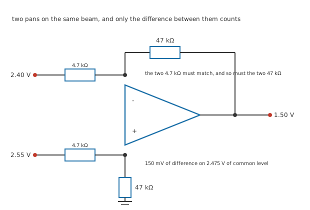
Three junction dots. The two 4.7 kΩ resistors must match each other, and so must the two 47 kΩ.
Split the network. Put 4.7 kΩ and 47 kΩ in the familiar inverting places, then hang a second, identical pair on the non-inverting input: 4.7 kΩ from the second source and 47 kΩ down to ground.
Worked example — What the difference amplifier does
The invented inputs are 2.40 V and 2.55 V, which differ by 150 mV and share a common level of 2.475 V.
The divider on the non-inverting input holds it at a fraction of the second signal, and the loop then does its usual work on the inverting side.
The output is 1.50 V, which is the difference multiplied by 10.0. The 2.475 V both inputs share contributes nothing.
That is a genuinely valuable thing to be able to do. A sensor at the far end of a cable produces a small difference riding on whatever the cable and the ground system have done to the common level, and this circuit throws the common part away.
Except that it only throws it away if the two halves match.
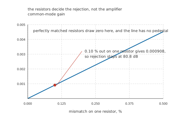
Through the origin with no pedestal: perfectly matched resistors reject perfectly.
Worked example — What one resistor being 0.10 % out costs
Leave three resistors exact and make one of the 47 kΩ pair 47.05 kΩ, which is 0.10 % high.
The two halves no longer balance, so a common-mode input now produces an output: the common-mode gain is 0.000908.
Against a differential gain of 10.0 that is a rejection of 11010 times, or 80.8 dB. The 2.475 V the inputs share appears at the output as 2.25 mV, which is 0.150 % of the signal.
Nothing in that calculation mentions the op-amp. The amplifier could reject common-mode perfectly and the answer would not change, because the imbalance is in the resistors and the amplifier is faithfully amplifying the difference the network handed it.
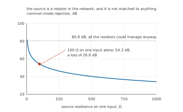
All four resistors perfectly matched. The fall is entirely the source's doing.
And the resistors are not all on the board
Here is the part that catches people, and it is the reason the next-but-two lesson exists.
Worked example — Where the fifth resistor comes from
Match all four resistors perfectly, then give one source 100 Ω of its own resistance.
It adds to that side's input resistor, so that half's gain becomes 9.79 while the other half's stays at 10.0. The common-mode gain jumps to 0.01894.
Rejection falls to 517 times, which is 54.3 dB and a loss of 26.6 dB, from a hundred ohms nobody drew.
There is a second problem hiding in the same place. The two inputs of this circuit do not present the same resistance to their sources: the inverting side presents 4.7 kΩ and the non-inverting side 51.7 kΩ, a factor of 11.0 apart. Two identical sensors driving the two inputs are therefore loaded differently, which unbalances the circuit before any source resistance is considered.
A difference amplifier is only as good as its resistors, and its resistors include the sources. Matched networks in one package exist for exactly this reason, and they are specified by their matching rather than their value. When even that is not enough, the answer is an instrumentation amplifier, which puts a buffer in front of each input so the sources never touch the matched network at all.
Common mistakes
- Expecting the channels of a summing amplifier to interact — they do not, because the node they share does not move. Sweeping one input gives the same slope whatever the others are set to, and the other channels only shift the line.
- Reading the weight off the input voltage — 5.0 V through 150 kΩ contributes 0.50 V while 1.0 V through 15 kΩ contributes 1.0 V. The weight is the feedback resistor divided by that channel's own resistor, and nothing else.
- Treating a difference amplifier's rejection as an op-amp specification — it is a resistor specification. 0.10 % on one resistor caps it at 80.8 dB no matter how good the amplifier is.
- Forgetting the sources are part of the matched network — 100 Ω on one input alone drops rejection from 80.8 dB to 54.3 dB, a loss of 26.6 dB, with all four resistors exact.
- Assuming both inputs load their sources equally — the inverting side presents 4.7 kΩ and the non-inverting side 51.7 kΩ, a factor of 11.0. Two identical sensors are therefore loaded differently.
- Using a difference amplifier where an instrumentation amplifier is needed — if the sources have any resistance, or any resistance you cannot control, the buffered version is not an upgrade but the only working answer.
Frequently asked questions
Can a summing amplifier have more than three inputs?
As many as you like. Each adds its own current to the same node and nothing about the existing channels changes. What eventually limits it is the noise gain: every added resistor lowers the feedback fraction, which lowers the loop gain and raises how much of the amplifier's own imperfections appear at the output.
Why is the summing amplifier's output negative?
Because it is an inverting amplifier with extra input resistors, and the inverting topology is the only one with a summing node. A non-inverting circuit has no node that stays still, so inputs added there interact with each other. If the sign matters, the usual fix is a following unity-gain inverting stage.
How well do resistors have to match for a given rejection?
Roughly, the rejection is the gain-plus-one divided by four times the fractional mismatch, and the figure here bears that out: 0.10 % on one of four resistors gives 80.8 dB. Every factor of ten better in matching buys another 20 dB, which is why matched networks are sold by their matching specification and cost far more than four ordinary resistors.
Does trimming one resistor fix the rejection?
It fixes it at one common-mode level, at one temperature, on one day. A trimmer can null the imbalance and it will drift back, because the trimmer and the fixed resistors do not track each other. It is a legitimate technique for a one-off instrument and a poor one for anything produced in quantity.
What if I only need to subtract, not amplify?
Then all four resistors are equal, the gain is one, and the matching requirement is at its most severe, because the rejection scales with the gain plus one. A unity-gain difference amplifier with 0.10 % resistors rejects considerably less well than the gain-of-ten circuit here, which is a good reason to take the gain in this stage rather than the next one.