
Quick Answer
A clipper puts a resistor in series and a diode in shunt, so the output stops following the input past a chosen level. A clamper puts a capacitor in series and the diode in shunt, so the whole waveform shifts until one extreme sits at that level. One changes the shape; the other changes the position.
Intuition
Trimming the hedge, and standing the pot on a box
Two ways to change how tall a plant looks. You can take the shears to it, which lowers the top and leaves the bottom where it was. Or you can stand the pot on a box, which raises the whole plant without touching a leaf. Both change the height of the topmost twig; only one changes the plant.
A clipper is the shears. It removes the part of a waveform beyond a chosen level and leaves the rest exactly as it was. The output has a flat top where the peak used to be, and its shape is genuinely different from the input's.
A clamper is the box. It shifts the whole waveform up or down until one of its extremes sits at a chosen level, and it does not touch the shape at all. Peak to peak, the output is identical to the input; only its position has moved.
The circuits are almost the same picture, which is why they get confused. Both are one series element and one shunt diode. Swap which element is in series and you have swapped which job the circuit does: a resistor in series makes a clipper, a capacitor in series makes a clamper. That one substitution is the whole difference, and this lesson is mostly about seeing why.
Practitioner
The clipper
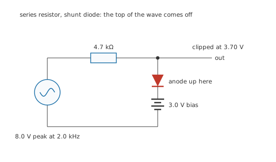
Series resistor, shunt diode: the top of the wave comes off.
The diode's anode faces the output node and its cathode sits on a bias supply. That means it conducts only when the input tries to push the node above the bias by more than a diode drop.
Worked example — Where a biased clipper cuts, and how much it removes
The bias is 3.0 V and the diode drops 0.70 V, so the clipping level is 3.70 V.
On an 8.0 V peak input at 2.0 kHz, whose period is 500 µs, the waveform first reaches that level 27.5 ° into the positive half-cycle.
Clipping therefore covers 34.7 % of the whole period.
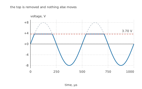
The top is removed and nothing else moves.
The series resistor is doing the work, not the diode. Once the diode conducts it holds the node at the clipping level, and the resistor takes the whole difference between the input and that level. Without it the source would be shorted to the bias supply through a conducting diode.
Worked example — What the resistor and the diode have to survive
At the input's peak the resistor has 8.0 V minus 3.70 V across it, so the diode carries 915 µA.
At its 0.70 V drop that is 640 µW in the diode, which is nothing.
Choose the resistor for the opposite reason: too small and the source works hard while clipping, too large and any load on the output forms a divider with it and pulls the unclipped part of the waveform down. 4.7 kΩ against the 100 kΩ load here loses under five percent.
Change the bias and the clipping level moves with it. Take the bias to zero and the diode clips at one drop above ground. Reverse the diode and it clips the negative half instead. Fit two, back to back with their own biases, and the waveform is limited both ways, which is the standard protection arrangement on an input pin.
Engineer
The clamper
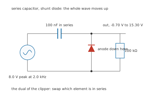
Series capacitor, shunt diode: the whole wave moves up.
Everything that made the clipper work is still here; the series element is now a capacitor.
The diode's anode faces the return rail, so it conducts whenever the output node tries to go below the rail by more than a drop. That pins the lowest point of the output, and because a capacitor cannot change the shape of what passes through it, pinning the lowest point moves everything else with it.
Worked example — Where the waveform ends up
On the first negative peak the diode conducts and charges the capacitor. In steady state the capacitor holds 7.30 V, which is the input peak less one diode drop.
The capacitor then simply adds that to everything, so the output runs from -0.70 V at the bottom to 15.30 V at the top.
Peak to peak the output is exactly the input. Only its position changed.
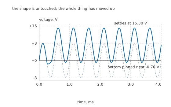
The shape is untouched; the whole thing has moved up.
The circuit takes a few cycles to get there. Simulating the same circuit from a discharged capacitor, the output has settled within 2.0 cycles and the capacitor reaches 7.22 V, a little short of the ideal 7.30 V because the load is drawing charge back out the whole time. That small deficit is the same effect as the droop below.
Droop, and the trade behind it
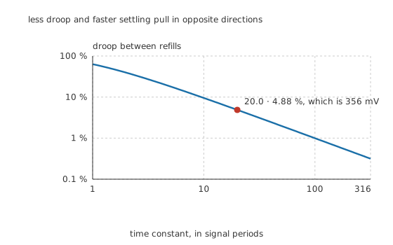
Less droop and faster settling pull in opposite directions.
Between one refill and the next, the load discharges the capacitor and the clamped level drifts.
Worked example — How far the level sags between refills
100 nF into 100 kΩ gives 10 ms, which is 20.0 signal periods.
Over one period the exponential decays by 4.88 %, which on 7.30 V is 356 mV of sag.
Ten times the capacitance gives a tenth of the droop, and ten times the settling time. That is the whole design decision, and it depends on the lowest signal frequency the circuit must handle rather than on the highest.
The 100 Ω the source presents while the diode conducts is what sets how fast the capacitor charges, and it is worth checking: a high-impedance source makes the clamp settle slowly and recover badly after an interruption.
Professional
Telling them apart, and using them
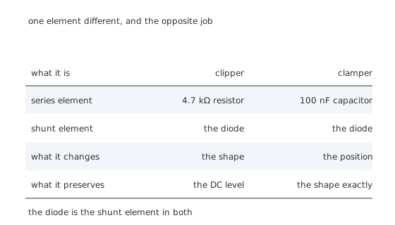
One element different, and the opposite job.
The single most useful diagnostic is to ask what the series element is. A resistor cannot store anything, so it can only divert current and change the shape. A capacitor cannot pass a steady voltage, so it can only shift the level and cannot change the shape. Nothing else about the two circuits matters as much as that.
A second check, if the drawing is unclear: look at what the output's peak-to-peak swing is. A clipper's is smaller than the input's. A clamper's is the same. If a circuit is described as a clamper and its output swing is not the input's, it is not doing what it says.
Where each one is actually used
Clippers protect inputs. Two diodes from a pin to the supply rails, or a pair back to back, limit whatever arrives to a little outside the rails. Almost every logic input already has a version of this built in, and the external resistor that makes it work is the series element this lesson describes.
Clippers shape waveforms. A sine clipped hard on both peaks becomes something close to a square wave, which is a cheap way to get a logic-level clock from an oscillator.
Clampers restore DC. A signal that has been through a coupling capacitor has lost its DC level, and a clamper puts a known one back. Video was the classic application: the black level of every line has to sit at a defined voltage, and a clamper does that once per line.
Clampers stack voltages. A clamper's output peak is nearly twice the input's, and that is exactly what the first stage of a voltage multiplier is. Seen that way, a multiplier is a clamper followed by a peak detector, repeated.
Four things that catch people out
A clamper needs a discharge path. With no load at all the capacitor never discharges, the clamp never adjusts, and the circuit locks at whatever the first cycle gave it. The load resistor is part of the circuit, not an afterthought.
A clamper is only as good as its lowest frequency. The droop calculation depends on the period, so a clamp designed for a kilohertz will sag badly at ten hertz. Signals with a varying frequency need the time constant sized for the slowest.
The diode drop offsets the clamp. The bottom of the output sits at -0.70 V, not at zero. Where that matters, the usual answers are a Schottky, which has a smaller drop, or a bias in the diode's return path to cancel it.
A clipper loads the source, and the load loads the clipper. The series resistor sits between both, and it cannot be optimised for one without affecting the other. Where the source cannot tolerate that, an active clipper built around an amplifier rather than a resistor is the answer.
Common mistakes
- Confusing the two circuits — the series element decides which is which: a resistor makes a clipper, a capacitor makes a clamper. The diode is the shunt element in both.
- Leaving out the series resistor in a clipper — the diode then shorts the source to the bias supply whenever it conducts, which is a fault rather than a circuit.
- Leaving a clamper unloaded — with no discharge path the capacitor cannot adjust, and the clamped level locks at whatever the first cycle set.
- Sizing a clamper's time constant for the wrong frequency — droop depends on the signal period, so a clamp designed at 2.0 kHz with 4.88 % of droop will sag far more at low frequencies.
- Forgetting the diode drop in the clamped level — the bottom of the output sits at -0.70 V, not at zero, and where that matters it needs a Schottky or a compensating bias.
Frequently asked questions
What is the difference between a clipper and a clamper?
A clipper removes part of the waveform and changes its shape, leaving its DC level alone. A clamper shifts the whole waveform up or down and leaves its shape exactly as it was. Circuit-wise, the difference is only which element is in series: a resistor for a clipper, a capacitor for a clamper.
How do I set the level a clipper cuts at?
By the bias voltage on the diode's far end plus one diode drop. A 3.0 V bias with a 0.70 V drop clips at 3.70 V. Take the bias to zero and it clips just above ground; reverse the diode and it clips the negative half instead.
Why does a clamper need a resistor in parallel with the output?
Because the capacitor has to be able to discharge as well as charge. Without a path the clamp cannot adjust when the signal changes, and its level locks at whatever the first cycle happened to set. The resistor's value, with the capacitor, sets both the droop and how quickly the clamp settles.
Does a clamper double the voltage?
It doubles the peak, not the swing. A waveform swinging 8.0 V either side of zero comes out running from about -0.70 V to 15.30 V: the same 16 V peak to peak, shifted up. Stacking that trick is exactly how a voltage doubler works.
How do I choose the capacitor in a clamper?
From the droop you can accept at the lowest frequency the signal contains. The time constant of the capacitor and the load, divided by the signal period, sets the droop directly: a ratio of 20 gives about 5 % per cycle. The cost of a larger capacitor is a proportionally slower settling time.