
Quick Answer
A voltage multiplier is a ladder of capacitors and diodes that adds twice the input peak to its output at every stage. It reaches high voltages from a modest source using parts rated only for one stage each, and pays for it with tiny available current and poor regulation.
Safety
A multiplier produces a voltage far above anything its source ever reaches, from parts that give no visual warning, and it stores that voltage in capacitors that stay charged long after the supply is removed. The four-stage ladder in this lesson reaches over two hundred and fifty volts from a twenty-four volt winding. Discharge every capacitor through a resistor and prove it dead with a meter before touching anything, and never assume that a low input voltage means a low output one. Multipliers connected to the mains have no isolation at all and are outside what this lesson covers.
Intuition
The enlargement made from an enlargement
Photocopy a picture at twice the size and you get something twice as big and slightly softer. Enlarge the copy again and you get four times the size, softer still. Repeat and the size keeps doubling while the quality keeps falling, and eventually it is enormous and useless.
A voltage multiplier runs the same scheme on voltage. Each stage adds twice the input's peak to what came before, so two stages give four peaks, four stages give eight, and there is no limit in principle. Each stage also adds ripple and makes the output sag harder under load, so the picture keeps getting bigger and keeps getting worse.
What makes the arrangement worth having is a detail that is easy to miss: no component in it ever sees more than about two peaks. A transformer that produced two hundred and fifty volts would need insulation rated for two hundred and fifty volts throughout. A ladder that reaches the same place is built entirely from parts rated for a small fraction of it, because each stage floats on top of the one below and only ever sees the difference.
That is why multipliers turn up wherever a high voltage is needed at almost no current: in the anode supply of an old television, in an ion generator, in a particle accelerator's injector, in a photomultiplier's bias chain. And it is why they are useless the moment real current is wanted.
Practitioner
One stage: the doubler
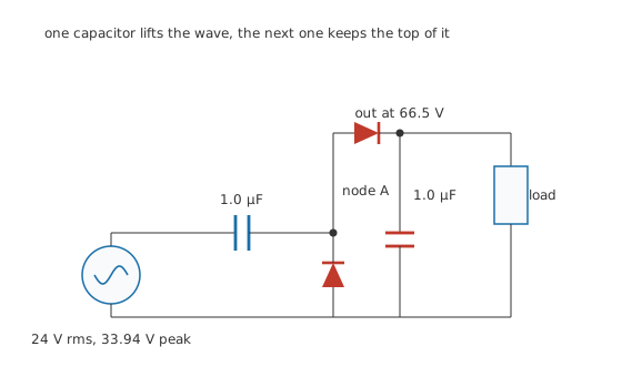
One capacitor lifts the wave, the next one keeps the top of it.
The whole ladder is this circuit repeated, so it is worth following once carefully.
On the negative half-cycle the source pulls node A down until the first diode conducts from the bottom rail into it, holding A one drop below the rail. The first capacitor therefore charges to nearly the source's peak.
On the positive half-cycle the source rises to its peak, and because the capacitor holds its charge, node A is carried up to nearly twice the peak. The second diode then passes that to the output capacitor.
Worked example — What one stage produces
A 24 V rms source peaks at 33.94 V.
Two diode drops of 0.70 V come off, so one stage delivers 66.5 V.
Simulating the same four components with a 1.33 MΩ load settles at 64.8 V, which is 2.58 % below the arithmetic. That shortfall is the load drawing charge back out between refills, and it is the first hint of what a longer ladder does.
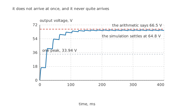
It does not arrive at once, and it never quite arrives.
The output does not appear immediately. Each cycle can only move the charge the diodes let through, so the capacitors fill over many cycles, and the approach is asymptotic. A multiplier switched on is not a supply that is ready.
Notice also that the source never sees the output. Its own peak is 33.94 V throughout, and the capacitor between it and the ladder is what carries the difference.
Engineer
The ladder
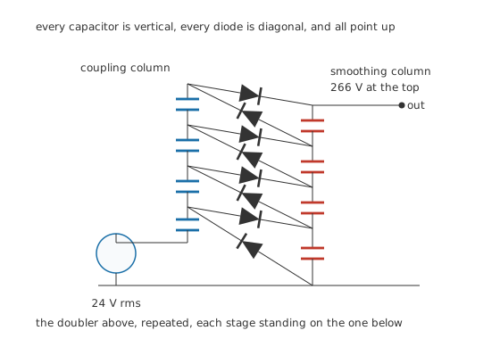
Every capacitor is vertical, every diode is diagonal, and all point up.
Stack the doubler and each stage does the same thing one level higher. The left column's capacitors couple the AC swing upward; the right column's smooth what arrives; the diodes zig-zag between them, and every one of them points the same way up the chain.
Worked example — What four stages reach
Each stage adds 66.5 V, so 4.0 stages give 266 V.
An ideal ladder with no diode drops would have given 272 V, so the eight drops cost about six volts in total.
Every diode in it holds off at most 67.9 V, twice the source's peak, whatever the output reaches. That is the property the whole arrangement exists for.
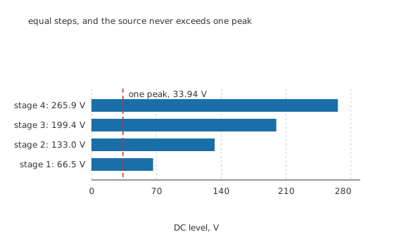
Equal steps, and the source never exceeds one peak.
What the stages cost
Each smoothing capacitor has to supply the load for a whole cycle before it is refilled, which is one contribution of ripple. The stages below it also have to resupply every stage above, so the contributions accumulate rather than simply adding.
Worked example — Ripple at four stages
With 1.0 µF capacitors, a 50 µA load and a 50 Hz supply whose period is 20 ms, one stage alone would ripple 1.0 V.
Over 4.0 stages the standard equal-capacitor result accumulates that to 10 V, which on 266 V is 3.76 %.
The load is only 50 µA and the load resistance is 5.32 MΩ. That is what "almost no current" means in practice.
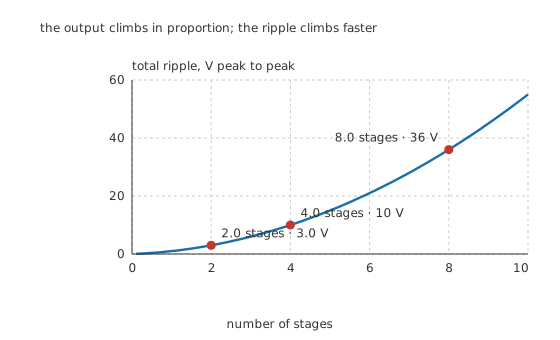
The output climbs in proportion; the ripple climbs faster.
The output rises in proportion to the stage count and the ripple rises as its square, so there is a stage count past which adding another one makes the supply worse rather than better. 2.0 stages here give 3.0 V and 8.0 give 36 V, which is about half a stage's worth of output.
The DC output also sags under load, and it sags much faster than the ripple grows. The standard analysis gives a drop that rises roughly as the cube of the stage count, so a ladder that looks fine unloaded can lose a large fraction of its output at a load a single rectifier would not notice. This lesson publishes no figure for it, because that polynomial is a result it has not verified first-hand, and a wrong number here would be worse than none. Measure it on the circuit you build.
Professional
Choosing it, and building it
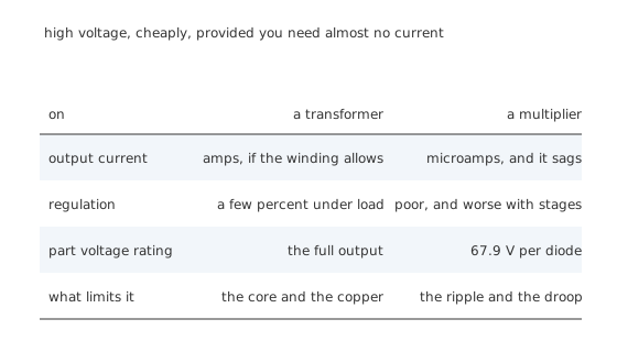
High voltage, cheaply, provided you need almost no current.
Use one where the current is microamps and the voltage is high. Photomultiplier and image-intensifier bias chains, electrostatic generators, ionisers, gas-discharge strikers, insulation testers. All of these want hundreds or thousands of volts and draw almost nothing, which is exactly the shape a ladder is good at.
Use one to avoid a high-voltage winding. Where the alternative is a transformer with heavy insulation and creepage clearances, the ladder is smaller, cheaper and safer to build, because nothing in it is rated for the full output.
Do not use one as a general-purpose supply. Its output impedance is high, its regulation is poor and both get worse with every stage. If the load draws milliamps, a transformer is the answer.
Five things to get right
Rate every capacitor for its own stage, not for the output. Each capacitor in the ladder sees roughly two peaks across it, the same as the diodes. Rating them all for the output voltage is a common and expensive mistake.
Drive it as fast as the source allows. The ripple and the droop both fall in inverse proportion to frequency, so a ladder driven at tens of kilohertz needs capacitors thousands of times smaller than one driven at 50 Hz. Almost every modern multiplier is driven from a switching oscillator for exactly this reason, and it is why they can be small.
Bleed it. The capacitors hold the output long after the supply is removed and there is nothing to discharge them. A permanent high-value bleeder resistor across the output is standard practice, and it is also a load, so it has to be counted in the ripple calculation.
Watch the corona and the creepage. A ladder reaching hundreds of volts needs the spacing to match, and the fact that no individual part is highly stressed does not mean the board is not. The top of the ladder is at the full output with respect to everything at the bottom.
Expect the ladder to fail from the top. The upper stages carry the most accumulated stress and the least margin, and a ladder with a failed upper stage still produces a lower output, so a multiplier that has quietly lost a stage looks like a supply that has drifted rather than one that has failed.
The half-wave and full-wave variants
The ladder in this lesson is the half-wave form, where the smoothing column carries a DC level and the coupling column swings. There is also a symmetric arrangement driven from both ends of the winding, which halves the ripple and the droop for the same parts because both halves of every cycle contribute. It costs a second column of capacitors and a centre-tapped or floating source, and where the source can provide that it is almost always the better choice.
Either way, the underlying idea is the one the clamper established: a capacitor in series shifts a waveform's level without changing its shape, and a diode decides where the shift stops. A multiplier is that trick applied repeatedly, each stage clamping to the level the stage below produced.
Common mistakes
- Rating the capacitors for the output voltage — each one sees only about two source peaks, 67.9 V here, whatever the top of the ladder reaches.
- Expecting useful current — this ladder holds 266 V into 5.32 MΩ, which is 50 µA. Draw more and the output falls away faster than the arithmetic suggests.
- Adding stages to fix a low output — the output rises in proportion but the ripple rises as the square and the droop faster still, so beyond a point another stage makes the supply worse.
- Leaving no bleeder — the capacitors hold the output indefinitely after the supply is removed, and nothing in the ladder discharges them.
- Assuming a low input means a low hazard — a 24 V winding produces over 250 V here, from parts that look entirely ordinary.
Frequently asked questions
How does a voltage multiplier work?
Each stage uses a series capacitor to shift the AC waveform up by whatever the stage below has already produced, and a diode to capture the new peak. Because the shift accumulates, every stage adds twice the source peak, less two diode drops, to the output.
What voltage do the parts in a multiplier have to withstand?
About twice the source's peak each, however high the output goes. Here that is 67.9 V per diode and roughly the same across each capacitor, on a ladder producing 266 V. That property is the whole reason multipliers are used instead of high-voltage windings.
How much current can a voltage multiplier supply?
Very little. This four-stage ladder with 1.0 µF capacitors at 50 Hz already has 10 V of ripple at 50 µA. Larger capacitors or a much higher drive frequency improve it in direct proportion, which is why modern multipliers are driven at tens of kilohertz rather than from the mains.
Why does adding more stages stop helping?
Because the output rises in proportion to the stage count while the ripple rises as its square and the loaded droop faster still. At some point another stage adds less useful DC than it adds wobble, and the exact point depends on the load, the capacitance and the drive frequency.
Is a voltage doubler the same as a multiplier?
A doubler is a one-stage multiplier. The doubler in this lesson takes a 33.94 V peak to 66.5 V, and a four-stage ladder is that circuit repeated with each stage standing on the one below. Everything true of the doubler is true of every stage of the ladder.