
Quick Answer
A series circuit connects components end to end so there is only one path for current, and the same current passes through every component in the chain. The voltage drops across the components add up to the source voltage, and their resistances add to give the chain's total resistance.
Intuition
A single path, end to end
Components are in series when they are joined one after another, the far end of one to the near end of the next, so that the circuit offers current a single route from one terminal of the supply back to the other. Nowhere along that route is there a fork or a junction where current could go a different way, so whatever passes through the first component has to pass through all of them.
Resistance adds along that route. A 120 Ω resistor followed by a 240 Ω resistor presents 360 Ω to the supply, and the current is then one number for the whole chain: put 9 V across it and 25 mA flows in both resistors alike.
What each component does have of its own is a share of the supply voltage. The 120 Ω resistor takes 3.0 V and the 240 Ω resistor takes 6.0 V; the two shares together account for the whole 9 V. The larger resistance took the larger share, in proportion to the resistances themselves.
Order along the chain changes none of this. Move a resistor from the front to the back and every reading stays where it was. What the chain contains is another matter: add a fourth component anywhere in it and every existing component sees less current than before, because the one path has become harder. Wiring components in parallel produces the opposite arrangement, where every component sits at the same voltage and the current is what divides.
Practitioner
Total the resistance first
A series problem is worked in a fixed order, and keeping to it removes most of the opportunity for error. Sum the resistances to find what the supply faces, divide the supply voltage by that sum to get the current, then carry that current back through each resistor in turn to find the drop it produces.
The formula is written out with three terms because that is what the worked example below needs; the rule is the same addition over as many terms as the chain contains. Values of wildly different size cause it no trouble. A large resistance in series with a small one dominates the total, and the small one barely shows there at all, though it carries exactly the same current as its large neighbour.
Worked example — A three-resistor chain, worked in order
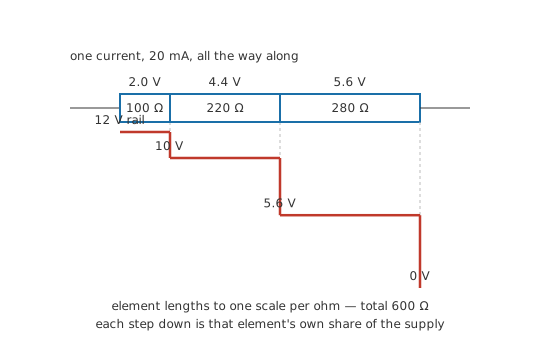
A supply of 12 V feeds three resistors joined end to end: 100 Ω, 220 Ω and 280 Ω.
Their sum is what the supply drives, R_s = 600 Ω. One current follows from that, I = V ⁄ R_s = 20 mA, and it is the current in all three resistors and in the supply lead as well.
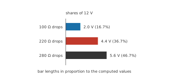
Each drop is that one current through that resistor's own resistance. V_1 = I × R_1 = 2.0 V, V_2 = 4.4 V, V_3 = 5.6 V.
Add the three drops and 12.0 V comes back, the supply figure to the last digit. A chain whose drops fail to sum to the source has an arithmetic slip in it, and this addition finds the slip faster than re-deriving the current does.
That the drops account for the source is Kirchhoff's voltage law showing up in its simplest setting, rather than an accident of these particular numbers. The law holds around any closed loop and gets its own lesson; a single-loop series chain is where it needs no bookkeeping at all.
Series chains turn up wherever something has to be fed a controlled current or denied a path. A resistor in series with an LED sets the LED's current by absorbing the difference between the supply and the LED's forward voltage, and a dropping resistor absorbs in the same way for a device fed from a rail higher than it wants. Insert a small sense resistor instead and the voltage across it reports the current through the load. Switches, fuses and thermal cutouts belong in the chain too, since breaking the one path is what they are for.
Measurement follows the same split. A voltmeter goes across the element whose drop you want and leaves the chain intact, while an ammeter has to be spliced into the chain, since that is the only way to make its own current the chain's current. Measuring V, I and R covers the technique, and Layer 4 comes back to what the splice does to the reading. Purely series and purely parallel circuits are the exception in any case, and series-parallel networks sets out the method for the rest.
Engineer
Charge does not pile up at a junction
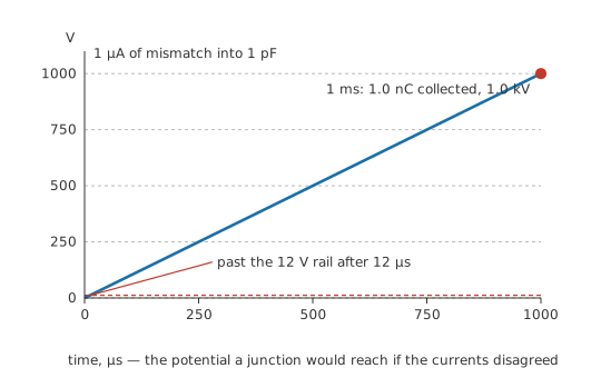
Take any point along a series chain and suppose, for a moment, that the current arriving there differed from the current leaving. The difference would be charge, accumulating at that point at the rate of the mismatch, and the point does have somewhere to put it — the stray capacitance between that piece of copper and everything around it, of order 1 pF for a small node.
Put numbers on a mismatch too small to measure. A shortfall of 1 µA sustained for 1 ms deposits 1.0 nC on the node, and a charge that size on a capacitance that small sits at 1.0 kV. That is far outside anything an ordinary circuit reaches, so the mismatch that would produce it never lasts: an imbalance that starts to develop builds a potential opposing itself within nanoseconds, and the two currents equalise.
Stated as a law, that is Kirchhoff's current law applied to the simplest node there is: the currents entering a junction sum to the currents leaving it, and a junction between two series components has one of each. Repeat the argument at every junction and one current has been established for the entire loop. The law constrains charge, not components, so it holds whatever sits in the chain — a resistor, a lamp and a motor in series carry identical current though nothing else about them matches.
The drops then follow with no further physics. Every element has the same I through it, so its drop is I × R_k, while I itself is the source voltage over the sum of all the resistances. Substitute the second into the first and I cancels: each element's drop is the source voltage scaled by that element's share of the total resistance. The third resistor of the Layer 2 chain holds 46.7 % of the total resistance, so it takes 46.7 % of the supply, which is the 5.6 V already found.
Written for two resistances, that ratio is the voltage divider:
Restricting the formula to two arms costs nothing, because any run of series elements above or below the tap sums into one arm. Lump the first two resistors of the Layer 2 chain into the upper arm, leave the third as the lower arm, and the divider returns 5.6 V, the same drop the step-by-step route produced.
Adding resistances presupposes that every element has a resistance to add, and the elements that break the presupposition announce themselves. A filament lamp's resistance climbs several-fold as it heats; a diode has a forward voltage rather than a resistance. Chains containing such elements still carry one current — charge conservation is indifferent to component type — but the current cannot be found by summing resistances. It comes from iteration, from the device's own curve, or from a simulator, and temperature effects are frequently the reason the number moves between the cold and warm cases.
The components are not the only things in the loop either. The copper joining them is in the chain as well, along with connector contacts and switch contacts, and it takes its own share of the supply — negligible at signal currents, and the dominant term when wire resistance meets amperes in a thin conductor.
And the account is a steady-state, lumped one throughout. The stray capacitance invoked above to prove the currents must match is the same capacitance that breaks the claim at high frequency: displacement current leaves a conductor along its length, so the current entering a wire genuinely differs from the current leaving it once the signal is fast enough. For DC, and for anything slow relative to the circuit's dimensions, one current in the loop is exact enough to design with.
Professional
Designing around a single point of failure
Protection belongs in the chain
A single path gives a single point of failure. Any element that goes open-circuit stops the current in every other element, while the rest of the chain goes on measuring healthy: sound parts and correct wiring, with no current anywhere in the loop. Design exploits that on purpose. Fuses, switches, thermal cutouts, emergency stops and machine interlocks are wired in series with the load so that one of them opening removes power from everything beyond it. A protective device wired across the thing it protects sits outside that thing's path, so opening it protects nothing.
The same property is a liability wherever it was not chosen. LEDs are wired in series so that one current-limiting resistor gives every die the same current, and so matched brightness; the same wiring also means one failed die takes the string dark. Cells in series behave alike: the pack delivers the current its weakest cell can supply, and the weakest cell is also the first to be driven into reversal by the others (battery packs in series and parallel).
Worst case against root-sum-of-squares
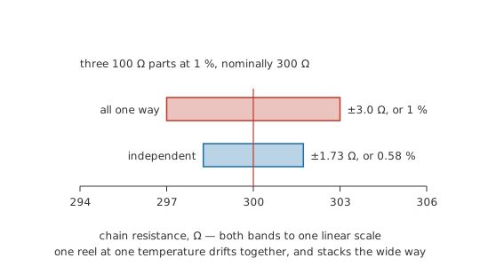
Tolerances stack along a chain, and how they stack depends on the question. Three 100 Ω resistors of 1 % tolerance give a nominal 300 Ω, and the worst case — every part at the same extreme — is 3.0 Ω away from nominal, which is still 1 % in relative terms. Treat the deviations as independent and combine them in quadrature instead, and the typical error is 1.73 Ω, or 0.58 % of nominal.
A guaranteed specification is written against the worst case. Root-sum-of-squares is what to expect across a production run, and it stays honest only while the deviations really are independent: parts from one reel at one temperature drift together, and correlated deviations stack the worst-case way.
Sharing a voltage no single part can take
Series connection also exists to divide stress. Put two parts in series and each sees a fraction of a voltage that would destroy either one alone, provided the fraction really is the one you assumed.
Worked example — Two capacitors across a DC bus
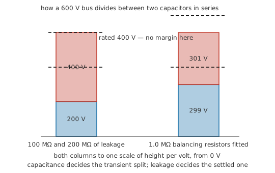
Two capacitors of equal nominal value, each rated 400 V, are put in series across a bus of 600 V. Nominally each holds half of it.
At DC it is leakage rather than capacitance that sets the split. Each capacitor is shunted by its own leakage resistance, and the two resistances form a divider across the bus. A two-to-one spread between parts of the same type is unremarkable, so take 100 MΩ and 200 MΩ.
The part with the higher leakage resistance ends up holding 400 V, its full rating with no margin left, while the leakier part sits at only 200 V. The better capacitor is the one in danger.
Wire 1.0 MΩ across each capacitor and the leakage spread stops mattering. The balancing resistors dominate the parallel combination at each position, and the split becomes 301 V against a nominal half. The cost is a permanent bleed current and the heat that goes with it.
Series-connected cells need the same treatment, which is what a battery management system's balancing function performs. Capacitors in series and parallel works through the capacitance side.
What an ammeter adds to the chain
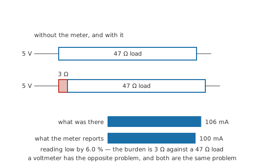
An instrument that measures current has to become part of the chain, and it brings its own resistance in with it. Take a load of 47 Ω on a 5 V rail, carrying 106 mA. Break the loop and insert a meter whose current range contributes 3 Ω of shunt, fuse and lead resistance, and the chain is no longer the chain you set out to measure: the meter reports 100 mA, low by 6.0 %. It is a correct reading of the circuit the insertion created.
The error is the burden resistance as a fraction of the chain total, so it grows as the circuit under test gets smaller. Where that matters, the usual answer is to leave the loop intact and infer the current from the voltage across a resistance already in it. Datasheets quote the effect as burden voltage; measurement accuracy treats it as the systematic error it is.
Safety
The capacitor example above exists only as arithmetic; no stack was assembled and none was probed. A series stack across a bus of several hundred volts stores energy that remains after the supply is removed, and balancing resistors bleed it away slowly, if at all — treat such a stack as live until it has been measured at zero. Inserting an ammeter is a separate hazard: on its current range a meter is close to a short circuit, and placed across a source instead of in series with a load it becomes one. The practices are in electrical safety fundamentals.
Common mistakes
- "The current gets used up along the way" — nothing is consumed in transit, and the current leaving the last component equals the current entering the first. Voltage is the quantity a series chain divides.
- Using the divider ratio at a tap that draws current. The proportional-drop result assumes one current in every element. Connect a load to the junction between two resistors and the upper and lower resistors no longer carry the same current, so the ratio no longer describes the tap voltage.
- Summing resistances for a chain that contains a lamp, a diode or a motor — those elements have no fixed resistance to sum. The chain still has one current; find it from the device's curve or by iteration.
- Leaving out the wiring, the connectors and the switch contacts. They sit in the chain with everything else. In a low-voltage, high-current loop they can take a bigger share of the source than the load does, and the symptom is a load that underperforms while every component measures good.
- Reaching for root-sum-of-squares because it gives the smaller number — it describes independent deviations. Parts from one reel at one temperature drift in step, and a guaranteed limit has to be written against the worst case.
Frequently asked questions
What stays the same in a series circuit, and what divides?
Current is common to every element; voltage divides between them. Each element takes a share of the source voltage in proportion to its own resistance, and those shares add back up to the source.
Why does adding a component in series reduce the current?
The one path becomes harder. Series resistances add, so the total the source drives goes up, and the current — the source voltage divided by that total — comes down. Every element in the chain, new and old, then carries the reduced current.
Does the order of components in a series chain matter?
The current is unaffected, and so is the size of each drop. What order does change is the voltage at each junction measured relative to ground, and it matters for safety and function as well: a switch or a fuse belongs at a point in the chain that has been chosen deliberately.
Why does one failed LED take out a whole series string?
An LED that fails open breaks the single path, and the string carries one current or none. The failure shows up as the full supply voltage appearing across the failed device, with no drop across any of the survivors.
How do I find the current in a chain containing a lamp or a diode?
Adding resistances will not do it, because neither part has a resistance to add. Use the device's current-versus-voltage curve together with the constraint that the drops must sum to the source — graphically as a load line, or numerically by iterating until the two agree.