
A reservoir capacitor across a rectifier's output holds the rail near the peak while the load draws current between humps. The remaining sag is the ripple, set by the load current, the ripple frequency and the capacitance. The cost is that the diodes now conduct in short, tall spikes.
Safety
A reservoir capacitor stays charged after the supply is switched off, and it holds that charge for as long as its own leakage and whatever is across it allow. Prove a supply is discharged before touching it rather than assuming, and never leave a large reservoir in a project without a bleed path. The figures here run at low voltage; the same arrangement inside mains equipment sits at hundreds of volts with no isolation, and it is the part of a dead appliance most likely to still be dangerous.
Intuition
The stone floor of a storage heater
A storage heater is a slab of dense brick that is warmed for a few hours overnight and then radiates all day. Nobody would call the heating steady if you watched the element: it is either full on or completely off. What makes the room comfortable is the mass of brick, which absorbs heat quickly while the element runs and gives it back slowly for the rest of the day.
Two things follow, and both have exact electrical counterparts. A bigger slab gives a smaller temperature swing for the same heating pattern, and a room that loses heat faster swings more for the same slab. Neither of those is a surprise, and neither depends on knowing anything about bricks.
A reservoir capacitor does the slab's job for a power rail. A full-wave rectifier hands the load a hump of voltage a hundred times a second and nothing in between. Put a capacitor across the output and it charges to the top of each hump and then supplies the load on its own until the next one arrives. The rail no longer falls to zero between humps; it sags a little and is topped up again.
That sag is the ripple, and it is what the whole of this lesson is about. Bigger capacitor, less sag. Bigger load, more sag. And one thing that does surprise people: the supply now delivers all of its current in short, tall bursts rather than steadily, which changes what the diodes and the transformer have to survive.
Practitioner
What the capacitor does
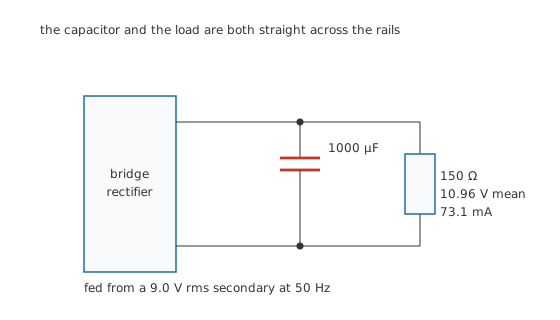
The capacitor and the load are both straight across the rails.
The capacitor goes directly across the rectifier's output, in parallel with the load and with nothing else in the way. That is the whole circuit change.
The relation is the capacitor's defining behaviour rearranged: a steady current drawn for a known time takes a known amount of charge out, and charge divided by capacitance is a voltage.
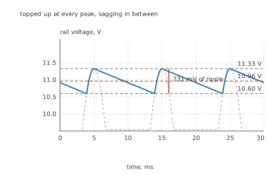
Topped up at every peak, sagging in between.
Worked example — The ripple on a 1000 µF reservoir
The 9.0 V secondary at 50 Hz peaks at 12.73 V, and after the bridge's two 0.70 V drops the capacitor charges to 11.33 V.
The load is 150 Ω, and the answer is circular: the ripple depends on the current, the current depends on the mean rail, and the mean rail depends on the ripple. Solving it gives a mean of 10.96 V drawing 73.1 mA.
With 1000 µF refilled at 100 Hz, the ripple is 731 mV peak to peak, so the rail runs between 11.33 V and 10.60 V. As a fraction of the output that is 6.67 %.
Notice how much better that is than the unsmoothed case. A bridge on its own averaged under two-thirds of the peak; with the capacitor the rail sits within a volt of the peak the whole time. The capacitor is doing more for the output than the extra two diodes did.
The decay between humps is a straight line rather than a curve, which is worth understanding. The time constant here is the capacitor and the load together, and the gap between humps is a small fraction of it, so the exponential has barely started to bend. Treating the discharge as a constant current is both simpler and accurate.
Engineer
What sets the ripple, and what it costs
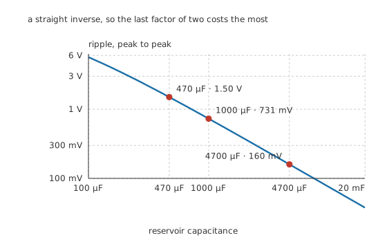
A straight inverse, so the last factor of two costs the most.
Worked example — Three reservoir sizes on the same load
Drop to 470 µF and the ripple rises to 1.50 V.
Go up to 4700 µF and it falls to 160 mV.
The relation is a straight inverse, so each halving of ripple costs a doubling of capacitance, and capacitors are priced by their capacitance and their voltage rating.
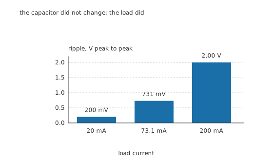
The capacitor did not change; the load did.
Ripple is directly proportional to load current, which has a practical consequence that catches people out. A supply measured at 20 mA shows 200 mV of ripple and looks excellent. Load it to 200 mA and the ripple is 2.00 V, ten times worse, and the circuit that worked on the bench now hums.
The other half of the relation is the ripple frequency, and it is why full-wave rectification matters so much here. Halving the gap between refills halves the ripple for the same capacitor, so switching from half-wave to a bridge is equivalent to doubling the reservoir for free.
The current the diodes actually carry
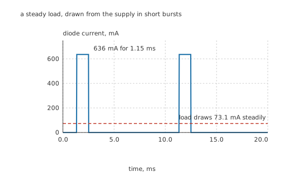
A steady load, drawn from the supply in short bursts.
This is the part that surprises everyone, and it is the reason a rectifier's diode ratings cannot be worked out from the load current alone.
The diodes can only conduct while the incoming hump is above whatever the capacitor has sagged to. Everything else about the design conspires to make that a short window: the smaller the ripple, the closer the capacitor stays to the peak, and the narrower the window becomes.
Worked example — How narrow the window is, and how tall the spike
The rail sags to 10.60 V, which the rectified sine passes on its way up only 20.69 ° before the peak. That is 1.15 ms out of every 10 ms, a duty of 11.5 %.
Over a full cycle the load removes 731 µC of charge, and all of it has to be put back inside that window.
So the diode current averages 636 mA while it conducts, which is 8.70 times the load current, and the instantaneous peak is higher still.
Everything follows from that ratio. The diode's repetitive peak current rating, not its average rating, is usually what binds. The transformer supplies far more rms current than the DC it delivers, so it has to be sized above the obvious figure. And the same spikes flow in the mains wiring, which is why capacitor-input supplies have a poor power factor and why regulations exist about it at any real power level.
Chasing lower ripple makes all of this worse. A larger reservoir narrows the conduction window and makes the spike taller for the same average, so there is a real limit past which the honest answer is a regulator rather than a bigger capacitor.
Professional
Choosing the capacitor
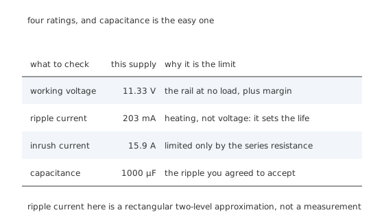
Four ratings, and capacitance is the easy one.
Voltage rating, at no load. The capacitor charges to 11.33 V under load, and with the load removed it charges closer still to the unloaded peak. Mains voltage is also allowed to run high. A 25 V part on an 11.33 V rail is not over-cautious, it is normal, and capacitor voltage ratings and derating explains why the margin is not optional.
Ripple current, which is a heating rating. The capacitor is charged in bursts and discharged continuously, so real current flows in it constantly. Approximating the two phases as rectangular gives 203 mA rms here. That current flows through the part's equivalent series resistance and heats it from the inside, which is what determines how long an electrolytic capacitor lasts. A part chosen only on capacitance and voltage will meet its ripple rating by accident or not at all.
Inrush, at the moment of switch-on. An empty capacitor is a short circuit. The only thing limiting the first charge is the resistance in the path: with 0.80 Ω of winding and diode resistance the first surge reaches 15.9 A. That is well inside the surge rating of an ordinary bridge, but scale the reservoir up and the same arithmetic is why larger supplies contain a thermistor or a relay-bypassed resistor to soften it.
Capacitance, which is the number everyone starts with. 1000 µF buys 731 mV on this load, and that is the whole calculation.
Where this design runs out
Ripple is proportional to load, so it is worst exactly when it matters. A supply that must hold a rail at full load has to be designed at full load, not at the load you happened to test with.
The mains is not a fixed voltage. A supply that just holds up at nominal mains fails at the bottom of the allowed range, and the rail rises at the top of it. The design point is minimum mains at maximum load for the low end, and maximum mains at no load for the capacitor's rating.
Beyond a certain point, add a regulator instead of capacitance. Once the ripple is a few percent, every further improvement costs a doubling of capacitance, a taller current spike and a worse power factor. A Zener regulator or an integrated regulator after the reservoir removes what is left far more cheaply, and it also removes the variation with mains voltage that no amount of capacitance touches.
The sensible division of labour is that the reservoir does the coarse job of turning humps into a rail, and something with feedback does the fine job of holding that rail steady. Trying to do both with one capacitor is the most common way a first power-supply design goes wrong.
Common mistakes
- Measuring ripple at light load and calling it done — ripple is proportional to load current, so 200 mV at 20 mA becomes 2.00 V at 200 mA on the same capacitor.
- Sizing the diodes from the load current — the bridge conducts for only 11.5 % of the time here, so it carries 8.70 times the load current while it does, and it is the repetitive peak rating that binds.
- Choosing the capacitor on capacitance and voltage only — ripple current is a heating limit that decides the part's life, and it has to be checked against the datasheet.
- Forgetting the no-load case — with the load removed the rail rises towards the unloaded peak, so the voltage rating has to cover that and not just the loaded 11.33 V.
- Solving for ripple with an assumed output voltage — the ripple, the load current and the mean output depend on each other, and assuming one of them without iterating gives an answer that is quietly wrong.
Frequently asked questions
How do I calculate the ripple on a smoothing capacitor?
Divide the load current by the product of the ripple frequency and the capacitance. For a full-wave rectifier the ripple frequency is twice the supply frequency. The answer is the peak-to-peak sag, and it assumes the capacitor discharges at a steady current, which is accurate when the gap between humps is short compared with the load's time constant.
What size smoothing capacitor do I need?
Work backwards from the ripple you can accept at full load. Multiply the load current by the time between humps and divide by the acceptable ripple. Then check the result against the voltage rating you need, the ripple current the part can take, and whether the resulting conduction spike is inside the diodes' repetitive peak rating.
Why do the rectifier diodes carry so much more current than the load?
Because they only conduct while the incoming waveform is above the capacitor's voltage, which is a small fraction of each cycle, and all of the charge the load takes over the whole cycle has to be delivered in that short window. Here the window is 11.5 % of the time and the current in it is nearly nine times the load current.
Does a bigger capacitor always help?
It reduces ripple in inverse proportion, but it also narrows the conduction window, which makes the current spikes taller for the same average, stresses the diodes and the transformer more, and worsens the power factor. Past a few percent of ripple, a regulator is usually the better answer than more capacitance.
Why does the rail sag in a straight line rather than an exponential curve?
It is an exponential, but only the very beginning of one. The time constant is the capacitor and the load together, and the gap between humps is a small fraction of it, so the curve has not had time to bend. Treating the discharge as a constant current is both simpler and, at these ratios, accurate.
Knowledge check
A bridge from a 9.0 V rms secondary feeds 150 Ω through a 1000 µF reservoir. What is the ripple? (Show answer)
The same supply is loaded to 200 mA instead. What happens to the ripple? (Show answer)
How much current do the bridge diodes carry, given a 73.1 mA load? (Show answer)
Why is the conduction window only 20.69 ° wide? (Show answer)
Besides capacitance and voltage, what has to be checked on a reservoir capacitor? (Show answer)
One email a month from the bench
New circuits, lessons, part guides and calculators, on the first Sunday of each month.