
A Zener regulator is a series resistor feeding a Zener diode and the load in parallel. The Zener absorbs whatever current the load declines, so the total through the resistor barely changes and the output stays near the Zener voltage. It is simple, wasteful, and only roughly regulated.
Intuition
The ballast that holds the waterline
A ship carries ballast so that it floats at the right depth whatever it is carrying. Unload cargo and you take on ballast water; load cargo and you pump ballast out. The total weight stays roughly the same, so the hull sits at the same waterline, and the ballast is doing nothing useful except making up the difference.
That is exactly a Zener regulator, including the uncomfortable part. A resistor from the incoming supply delivers a roughly fixed current. A Zener diode sits across the output alongside the load. When the load takes little, the Zener takes a lot; when the load takes more, the Zener takes correspondingly less. The total stays put, so the voltage across the pair stays put, and the output is regulated.
The cost is the same cost the ship pays. The ballast is dead weight, and the Zener's share of the current is dissipated as heat for no benefit. Worse, the arrangement wastes the most when the load is doing the least, which is the opposite of what anybody wants.
Two components and one afternoon will give you a usable rail this way, and that is a genuinely good reason to know how. But the arrangement has a ceiling, and knowing where it is matters as much as knowing how to size the resistor.
Practitioner
Sizing the two components
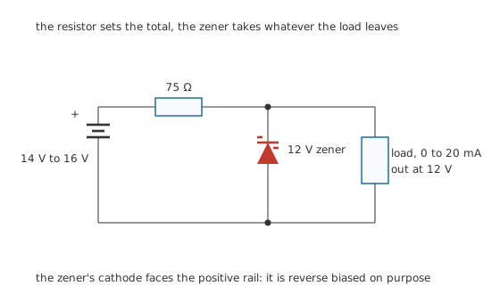
The resistor sets the total, the Zener takes whatever the load leaves.
The design has two unknowns, the resistor and the Zener's power rating, and each is set by a different worst case.
Worked example — Sizing the resistor at the worst corner for it
The design has to work at the lowest input, 14 V, with the largest load, 20 mA, and still leave the Zener at least 5.0 mA so it stays off its knee.
Adding those two currents and dividing them into what the resistor has across it gives 80 Ω.
A real value has to be at or below that, so 75 Ω is the choice. At that value the same corner passes 26.7 mA in total and leaves the Zener 6.67 mA, comfortably above the minimum.
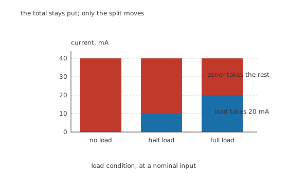
The total stays put; only the split moves.
At the nominal 15 V input the resistor passes 40.0 mA. With the load taking 20 mA, the Zener takes 20.0 mA. Remove the load entirely and the Zener takes the lot.
Worked example — Sizing the Zener at the worst corner for it
The Zener's worst case is the opposite corner: highest input, no load.
At 16 V the resistor passes 53.3 mA, and with no load all of it goes through the Zener.
That is 640 mW of dissipation, so a 1.0 W part is needed, and the half-watt part that would have looked adequate from the load alone would fail.
The resistor, meanwhile, dissipates at most 213 mW, so a quarter-watt part covers it.
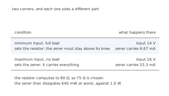
Two corners, and each one sizes a different part.
Checking one corner and not the other is the standard way this circuit fails, and it fails in a way that is easy to miss: the supply works perfectly on the bench with the load connected, and cooks the Zener the first time somebody unplugs the thing it was feeding.
Engineer
How well it actually regulates
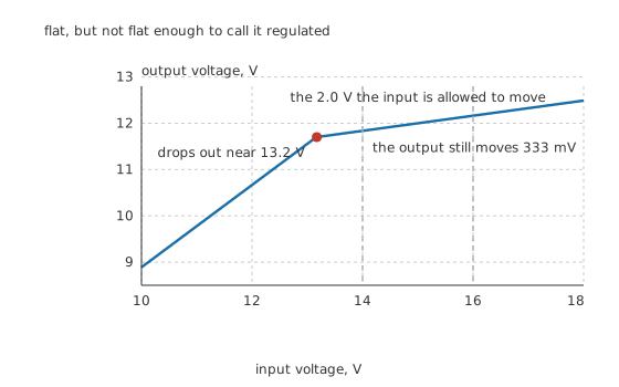
Flat, but not flat enough to call it regulated.
The word "regulated" does a lot of work here, and the arithmetic is unforgiving.
Line regulation is a divider ratio and nothing more. A change on the input arrives at the output divided between the series resistor and the Zener's slope impedance.
Worked example — What input variation reaches the output
The Zener's slope impedance is 15 Ω, quoted at a test current of 20 mA, against a series resistor of 75 Ω.
A change on the input is therefore divided by 6.00, so the 2.0 V the input is allowed to move produces 333 mV at the output.
Improving that means a larger series resistor, which means less current available for the load, which is the trade the whole circuit is built on.
The curve above is computed by solving the node equation with the Zener modelled as a source of 11.70 V behind its slope impedance, in parallel with the 600 Ω the full load represents. Below about 13.2 V the circuit stops regulating altogether. The Zener falls out of breakdown, contributes nothing, and the circuit becomes a plain resistive divider whose output follows the input straight down. That knee is real and visible on the curve, and it is why the minimum-input corner has to be a genuine minimum rather than a hopeful one.
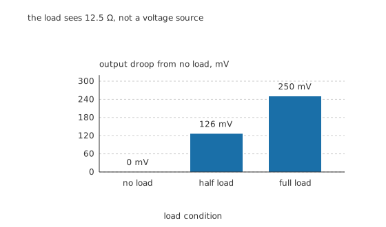
The load sees 12.5 Ω, not a voltage source.
Load regulation is the same divider seen from the other side. As far as the load is concerned, the source is the Zener's slope impedance in parallel with the series resistor.
Worked example — What the load sees
The output impedance is 75 Ω in parallel with 15 Ω, which is 12.5 Ω.
Drawing the full 20 mA through that costs 250 mV.
Adding the two effects, the output can sit anywhere across 583 mV, or 4.86 % of nominal, before the Zener's own tolerance is even considered.
That last sentence is the honest summary of the circuit. Around five percent, on a part whose nominal value is itself only guaranteed to five percent. It is a rail, not a reference.
Professional
What it costs, and when to stop using it
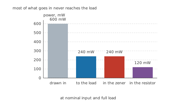
Most of what goes in never reaches the load.
At the nominal point the circuit draws 600 mW and delivers 240 mW, an efficiency of 40.0 %. The Zener burns 240 mW and the resistor 120 mW.
Now disconnect the load. The input power barely changes, because the resistor still passes the same current, and the useful output is zero. A shunt regulator draws its full input power whether or not anything is using it, and in a battery-powered design that single fact usually rules it out.
The three places it is genuinely the right answer
Where the load is small and constant. A reference voltage for a comparator, a bias point, or the supply for a low-power op-amp. The waste is milliwatts and the parts count is two.
Where it is a pre-regulator. Feeding the reference pin of something better, or providing a rough rail for the control circuitry of a larger supply.
Where it also has to clamp. A shunt regulator naturally limits the output if the input rises, which a series regulator does not, so it doubles as protection for whatever it feeds.
Where to stop
Above about a hundred milliwatts of waste, a series regulator wins on every count: the pass element only carries the load current, so the waste falls to zero when the load does.
When the input range is wide. The line ratio here is only 6.00, and widening the input range widens the output range in direct proportion. A regulator with feedback rejects input variation by factors of thousands rather than by six.
When accuracy matters. Adding the tolerance of the Zener to the 4.86 % computed above gives a rail that is guaranteed to about a tenth of its value, which is fine for a relay coil and useless for an analogue-to-digital converter's reference.
Two improvements that are worth knowing
Feed the resistor from a stiffer supply. Most of the line variation this circuit passes comes from the input moving. Putting the shunt regulator after a smoothing capacitor big enough to keep the ripple small does more for the output than any change to the Zener.
Add an emitter follower. Buffering the Zener's node with a transistor lets the Zener run at a steady, small current while the transistor carries the load. The output impedance drops by the transistor's current gain and the waste falls to the load current alone. That is the standard next step, and it is why the plain two-component circuit is best understood as the reference stage of something slightly larger rather than as a finished supply.
Common mistakes
- Sizing the resistor only at the nominal input — it has to pass enough current at minimum input with maximum load, or the Zener falls off its knee and the rail collapses.
- Sizing the Zener only at full load — its worst case is no load at maximum input, where it carries everything the resistor passes: 53.3 mA and 640 mW here.
- Expecting a regulated rail — the input's variation is divided by only 6.00, and the output moves 583 mV in total, which is 4.86 % before the Zener's own tolerance.
- Using one where the load varies widely — the output impedance is 12.5 Ω, so every milliamp of load change moves the rail by more than twelve millivolts.
- Forgetting that the input power is constant — the circuit draws the same current with the load disconnected, so its efficiency at light load is essentially zero.
Frequently asked questions
How do I choose the series resistor in a Zener regulator?
At the worst corner for it, which is minimum input voltage with maximum load current. The resistor must still pass the load current plus enough Zener current to keep the part above its knee. Compute the ideal value there and choose a real value at or below it, then re-check every other condition with the value you actually chose.
What power rating does the Zener need?
Enough for the opposite corner: maximum input voltage with no load, where the Zener carries the entire current the resistor passes. In the circuit here that is 53.3 mA at 12 V, which is 640 mW, so a 1 W part is needed even though the load never takes more than 240 mW.
How well does a Zener regulator hold its output?
Poorly, by the standards of anything with feedback. Input variation is divided only by the ratio of the series resistor to the Zener's slope impedance, six here, and the load sees an output impedance of 12.5 Ω. The total variation across the design's operating range is 583 mV on a 12 V rail.
Why does the output follow the input below a certain voltage?
Because the Zener has fallen out of breakdown and is no longer conducting, so it contributes nothing. The circuit becomes a plain resistive divider made of the series resistor and the load, and its output rises and falls with the input until the Zener starts conducting again.
Is a Zener regulator ever better than an integrated regulator?
For very small, steady loads where two components and no quiescent-current specification matter more than efficiency, and where the natural clamping behaviour is useful. It is also the reference stage inside many larger supplies. For anything drawing real current, or with a wide input range, or needing accuracy, it is not competitive.
Knowledge check
A 12 V Zener regulator runs from 14 V to 16 V and feeds up to 20 mA. What series resistor is needed? (Show answer)
What power rating does the Zener need, and why is that not set by the load? (Show answer)
How much of the input's 2.0 V variation reaches the output? (Show answer)
What does the load see looking back into a Zener regulator? (Show answer)
How efficient is this regulator, and what happens when the load is removed? (Show answer)
One email a month from the bench
New circuits, lessons, part guides and calculators, on the first Sunday of each month.