
Quick Answer
A voltage reference exists to be accurate rather than useful. It holds one voltage against temperature, time and supply changes, supplies almost no current, and is the thing every measurement in a circuit is ultimately compared against. A regulator powers a load. A reference is read.
Intuition
Read it, do not draw from it
Every toolroom has a drawer nobody works out of. In it are the master gauges: blocks and plugs and rings held to a tolerance far finer than anything the shop actually makes, kept clean, kept at a known temperature, and never used to cut anything. Their whole job is to be the thing other tools are checked against.
Nobody thinks this is a waste. A gauge that got used would wear, and a worn gauge would carry the wear into every part measured with it afterwards, silently.
A voltage reference is that drawer. It is a part whose only purpose is to hold one number, accurately, for years, while nothing much is asked of it. It will not run your circuit. It has no business supplying a load. What it does is give the comparator, the converter or the regulator something to be right about — and the accuracy of everything downstream is capped by it.
A linear regulator contains one and hides it. What that lesson called an internal reference is this: a small, careful, deliberately unhelpful voltage that the loop copies and scales. Pulling it out and looking at it is what this lesson does.
Practitioner
Two ways to build one, and a resistor tells them apart
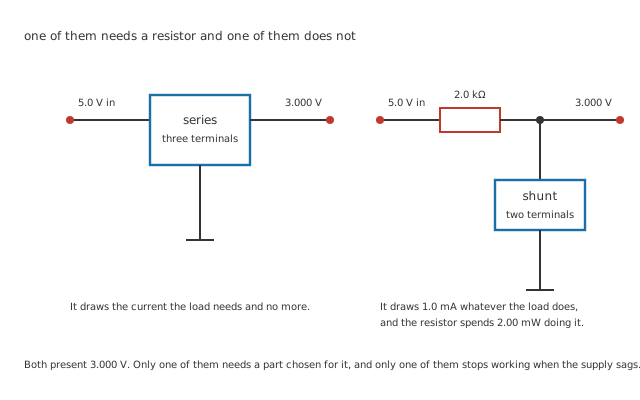
One junction dot, at the only three-way meeting in the figure.
References come in two arrangements and the difference is visible from across the room.
A series reference is a three-terminal part: supply in, reference out, ground. It behaves like a very small, very careful regulator, and it draws roughly what the load needs plus its own quiescent current.
A shunt reference is a two-terminal part that sits from the output node to ground and does nothing but hold that node at its voltage by swallowing whatever current arrives. It cannot work alone: something has to feed the node, and that something is a resistor.
Worked example — Sizing the resistor a shunt part needs
A 3.000 V shunt reference on a 5.0 V supply leaves 2.000 V across the resistor.
Give the reference 1.0 mA to work with and the resistor is 2.0 kΩ, spending 2.00 mW.
It spends that whether or not anything is reading the output, and it must go on supplying 1.0 mA even at the lowest supply the circuit will ever see.
That last sentence is where shunt references go wrong. The resistor is sized at the nominal supply, the supply sags, the current through the resistor falls below what the reference needs to regulate, and the output collapses without anything obviously failing.
Where the voltage comes from in the first place
Most modern references are bandgap parts, and the name is a physical claim rather than a brand. Two things inside a chip drift in opposite directions with temperature: a transistor's base-emitter voltage falls, and the difference between two such voltages at different current densities rises. Add them in the right proportion and the drift cancels.
What is left when it cancels is not arbitrary. It comes out near 1.205 V, the bandgap of silicon extrapolated to absolute zero, because that is the quantity the cancellation is built out of. It is a material constant, not a specification, and it is why so many references and regulator cores sit close to 1.2 V — including the invented 1.205 V core behind entry one's regulator.
An invented reference carries the rest of this lesson: 3.000 V out, 0.10 % of initial accuracy, 25 ppm/°C of temperature coefficient, 50 ppm of long-term drift per thousand hours, 12 µV of low-frequency noise and 0.20 Ω of output impedance. Every one of those numbers is an invention and belongs to no catalogue part.
Engineer
Four things move it, and usually one of them dominates
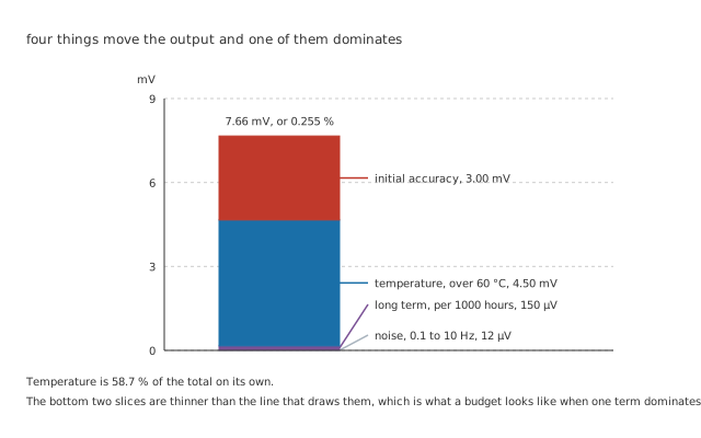
The bottom two slices are thinner than the line that draws them.
"Accurate to 0.1 per cent" is the number on the front page, and it is the smallest of the four things that will move the output.
Worked example — Adding up one reference's error
Initial accuracy is how far off it was on the day it was made: 0.10 % of 3.000 V, or 3.00 mV.
Temperature is 25 ppm/°C. From 25 °C up to 85 °C is 60 °C, which gives 4.50 mV. The cold end, down at -40 °C, is 65 °C away and gives slightly more.
Long-term drift is 50 ppm per thousand hours: 150 µV. Noise adds 12 µV.
Together, 7.66 mV, or 0.255 % — and temperature is 58.7 % of it on its own.
Notice which of those numbers the datasheet's headline gave you. The initial accuracy is a real specification and it is also the one that matters least, because it is a fixed offset you can calibrate out once. The temperature coefficient is not something you can calibrate out, because it changes as the room does.
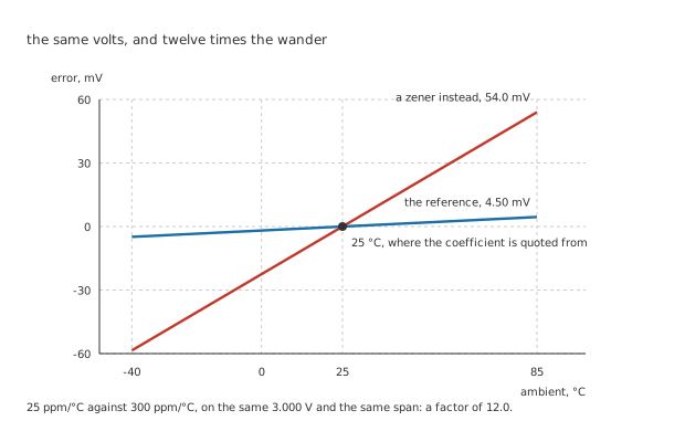
Both are zero at 25 °C by definition, and the cold end is further from it than the hot end.
Worked example — What a zener would have done instead
Take the same 3.000 V and hold it with a zener at an invented 300 ppm/°C.
Over the same 60 °C that gives 54.0 mV of movement.
Which is 12.0 times the reference's 4.50 mV, from a part that costs a fraction as much and is entirely adequate where nothing is being measured.
A zener is not a bad component here. It is a clamp being asked to be an instrument, and the factor of 12.0 is the price of that mismatch rather than a fault.
Buying a better coefficient, and where it stops paying
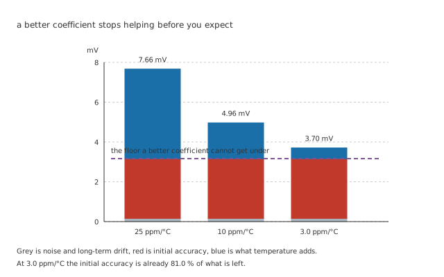
Grey is noise and drift, red is initial accuracy, blue is what temperature adds.
The same family usually offers several coefficient grades, and the temptation is to take the best one available.
Worked example — Three grades of the same part
At 25 ppm/°C the temperature term is 4.50 mV and the total is 7.66 mV.
Take 10 ppm/°C and the term falls to 1.80 mV, the total to 4.96 mV. Take 3.0 ppm/°C and it falls to 540 µV and 3.70 mV.
But the initial accuracy has not moved, and at the finest grade it is 81.0 % of what is left.
Past that point a better coefficient is buying almost nothing, and the money is better spent on calibrating the offset out — which removes the largest remaining term entirely and costs nothing in parts.
Professional
Using one without spoiling it
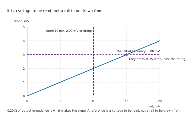
The crossing is past the rating, which is the reassuring half of the story.
Worked example — What loading it actually costs
The reference has 0.20 Ω of output impedance, so drawing its rated 10 mA droops the output by 2.00 mV.
That is smaller than its own 3.00 mV, and the two are not equal until 15.0 mA.
So within the rating, loading is the least of the four errors. Past the rating there is no specification at all, and the part stops regulating rather than degrading gracefully.
The practical rule follows from the arithmetic rather than from caution: draw what the datasheet allows and no more, and where a rail is wanted rather than a voltage, buffer it. A unity-gain amplifier between the reference and the load costs one part and moves the whole problem into a device built to supply current.
What the reference is actually worth downstream
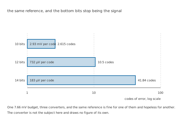
The converter is not the subject here and draws no figure of its own.
A reference's error is not interesting in millivolts. It is interesting in whatever the circuit downstream counts in.
Worked example — The same reference, three converters
Use the reference as a converter's full scale. At 1024 steps one code is 2.93 mV, so the 7.66 mV budget is 2.615 codes.
At 4096 steps a code is 732 µV and the budget is 10.5 codes. At 16384 steps a code is 183 µV and it is 41.84.
The part has not changed. What changed is how many of the bottom bits are reporting the reference instead of the signal.
This is the calculation that decides whether a reference is good enough, and it is why "which reference" is never a question with an answer on its own. It needs the resolution, the temperature range and whether the offset gets calibrated out. The converter's own errors sit on top of these and are a separate subject.
Reading one on a schematic
Find out whether it is series or shunt. Two terminals and a resistor above it is a shunt part, and that resistor is a design decision that has to survive the lowest supply.
Check what is loading it. A reference feeding anything with an appreciable input current is a reference being asked to be a regulator.
Look for the bypass capacitor, and then look up whether it is allowed. Some references need one, some tolerate one, and a few oscillate with one — which is the same loop-stability question a regulator's output capacitor raises, in a part where nobody expects it.
And check the ground. A reference is only as good as the ground it is measured against, and a few millivolts of drop in a shared return undoes every ppm you paid for.
Common mistakes
- Reading the initial accuracy as the accuracy — 0.10 % gives 3.00 mV, and temperature adds 4.50 mV on top of it. The headline number is 39 % of a 7.66 mV budget.
- Buying the finest coefficient grade without calibrating — at 3.0 ppm/°C the initial accuracy is already 81.0 % of what is left, so the grade below it costs less and gets you nearly as far.
- Using a reference as a small supply — 0.20 Ω of output impedance and a 10 mA rating are not a rail. Past the rating there is no specification at all, and the answer is a buffer rather than a bigger reference.
- Sizing a shunt reference's resistor at the nominal supply — 2.0 kΩ delivers 1.0 mA from 5.0 V and less from anything lower. When the current falls below what the part needs, the output collapses without a component failing.
- Comparing coefficients quoted at different temperatures — 25 ppm/°C means nothing without the span it is quoted over, and every coefficient is zero at its own calibration point by construction.
- Ignoring long-term drift on anything that stays in service — 50 ppm per thousand hours is 150 µV here, which is small, and it does not stop after the first thousand hours.
Frequently asked questions
Why is the temperature coefficient in parts per million rather than millivolts per degree?
Because it scales with the reference voltage, and expressing it as a fraction lets one number describe a whole family. A 25 ppm/°C part at 3.000 V moves 75 µV per degree; the same grade at 5 V moves 125 µV per degree, and the ppm figure is the same in both. It is also how the number gets compared with initial accuracy and long-term drift, both of which are naturally fractional.
Is a reference's coefficient really a straight line?
No, and the figure above draws it as one deliberately. A real reference's error against temperature is a shallow curve, sometimes with a turning point somewhere in the range, and the quoted coefficient is usually the total excursion divided by the span rather than a slope at any particular temperature. That definition — box method, in most datasheets — is why two parts with the same number can behave differently, and why the definition is worth checking.
Can I calibrate out the temperature coefficient too?
Only if you measure the temperature, which is a much larger undertaking than measuring the offset once. Storing a correction against a temperature sensor is done in precision instruments and it works. For most designs it is cheaper to buy a better coefficient, and the point at which that stops being true is exactly where the initial accuracy starts dominating.
Why do some references specify a minimum load?
Because their internal loop needs some current flowing to stay in control, and with nothing drawn the output can sit above its nominal value or become unstable. It is more common on shunt parts, where the bias current serves that purpose, and it is one of the few places a datasheet asks you to waste current deliberately.
What is the difference between a reference and a regulator, really?
What they are optimised for. A regulator is judged on how much current it delivers and how steady it stays while delivering it; a reference is judged on how little it moves over years and degrees. Both hold a voltage with a feedback loop, and a regulator contains a reference. The 10 mA rating here against a regulator's 150 mA is the whole distinction in one number.