
Quick Answer
A phototransistor is a bipolar transistor whose base is illuminated rather than wired, so light sets its collector current and the device's own gain multiplies it. An optocoupler seals one facing an LED, letting a signal cross a barrier that no conductor crosses.
Intuition
A message through a window that never opens
Two rooms with a sealed glass panel between them can still exchange messages. Somebody holds up a card on one side and somebody reads it on the other. Nothing passes through the glass — no air, no sound, no cable — and yet information arrives.
An optocoupler is that arrangement in a plastic package. On one side an LED lights up when current is put through it. On the other, a phototransistor sees the light and conducts. Between them is a transparent insulator, and no conductor of any kind joins the two halves.
That matters wherever two parts of a system must not share a ground. A microcontroller talking to something on a mains-referenced supply. A measurement made at one potential and read at another. Any signal path where a fault on one side must not put a voltage on the other.
The phototransistor is worth understanding on its own too, because it is simply a transistor whose base connection has been replaced by a window. Light arriving at the base region generates carriers, those carriers act as base current, and the transistor's own gain multiplies them — which is why a phototransistor is far more sensitive than a bare photodiode.
That gain is not free. The same mechanism that multiplies the signal also multiplies the time constant, which is why these parts are slow. A photodiode is quick and produces little; a phototransistor produces a lot and takes microseconds about it.
Practitioner
The two halves, and what joins them
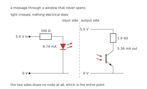
Light crosses; nothing electrical does.
Worked example — One signal across the gap
Driving the input from 5.0 V through 390 Ω, with the LED holding 1.2 V, gives 9.74 mA through the emitter.
At that drive this device's transfer ratio is 0.550, so the phototransistor passes 5.36 mA.
Through 1.0 kΩ that is more than enough to pull the output down hard, since saturating that load takes only 5.0 mA.
The transfer ratio is the whole specification. It is the output current divided by the input current, usually quoted as a percentage, and it is the number every calculation about the part goes through. It is not a gain in the transistor sense — it combines the LED's efficiency, the geometry of the gap, and the transistor's sensitivity and gain into one figure.
That figure is also the part's weakness. Where a transistor's current gain varies by a factor of three across a part number, an optocoupler's transfer ratio varies by more, drifts with drive current, and falls steadily over the part's life.
Engineer
The three ways the transfer ratio moves
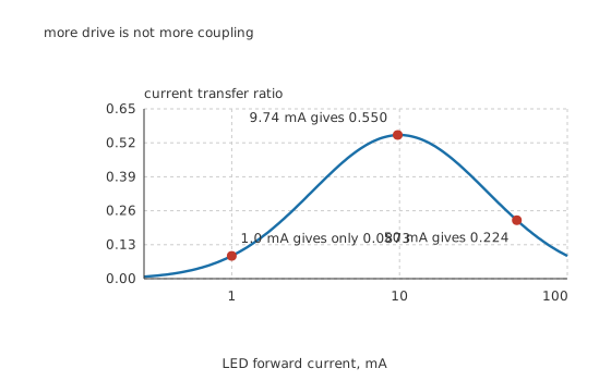
More drive is not more coupling.
Worked example — It peaks, and both directions are downhill
This device peaks at 0.55 near 10 mA, which is where 9.74 mA lands and gives 0.550.
Run the LED at 1.0 mA instead and the ratio collapses to 0.0873 — 6.30 times worse.
Run it at 50 mA and it falls again, to 0.224, because the LED's own efficiency drops as it heats and the transistor's gain falls at higher current.
Driving the input harder to get more output stops working, and then reverses. That is not intuitive and it is the most common design error with these parts.
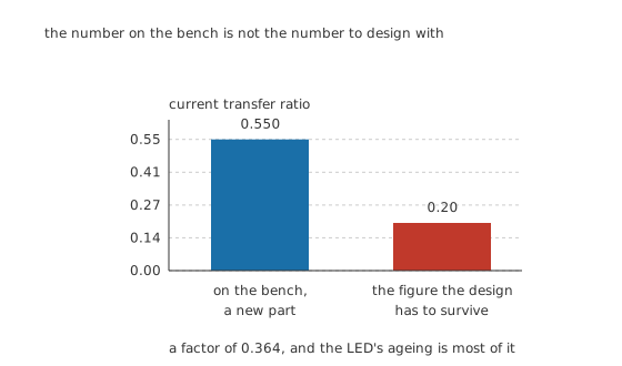
The number on the bench is not the number to design with.
Worked example — Designing for the part you will have in ten years
A fresh device gives 0.550. Across a manufacturer's distribution and over the LED's working life, a design has to assume something like 0.20 — a factor of 0.364, and most of that is the LED dimming rather than the transistor changing.
Saturating the 1.0 kΩ load needs 5.0 mA, so at the worst-case ratio the LED needs 25 mA, through 152 Ω.
That is 2.57 times the drive a fresh part would have needed. A prototype that works on the bench with a comfortable margin can still fail in service, and the arithmetic that prevents it takes one line.
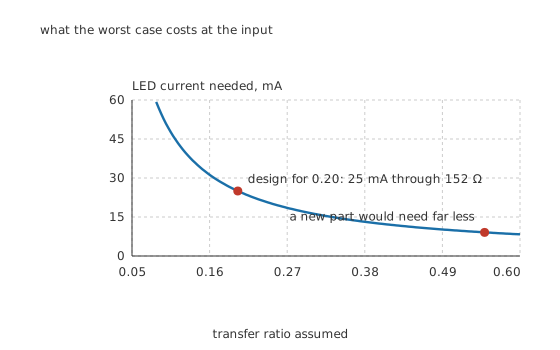
What the worst case costs at the input.
There is a limit to that margin, and it is visible on the first figure: driving the LED past its peak makes the ratio worse, so the current cannot simply be increased indefinitely. Where the required margin runs past the peak, the answer is a different part rather than more current.
Professional
Speed, isolation, and the same device used differently
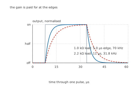
The gain is paid for at the edges.
Worked example — Why the load resistor sets the speed
Into 1.0 kΩ this part's edge takes 5.0 µs, which limits it to about 70 kHz.
Into 2.2 kΩ the same part takes 11 µs and manages only 31.8 kHz.
The load resistor is charging the transistor's own capacitance, and that capacitance has been multiplied by the transistor's gain before the load sees it. A smaller load resistor is faster and gives less output swing, and that is the whole of the trade.
Where speed matters, the answer is not a better phototransistor. It is a different output stage: a photodiode with an amplifier after it, or a logic-output optocoupler that contains one. Those reach megahertz where this arrangement reaches tens of kilohertz.
What the isolation rating is, and why no number appears here
The barrier's rating is the reason the part exists, and it is exactly the kind of figure this lesson will not print. Withstand voltages, creepage and clearance distances, working voltages and pollution degrees are safety-agency numbers, tied to a named standard, a specific part and a specific test method, and they are revised.
What can be said generally: the rating is a property of the part and its package, not of the circuit; a transient rating and a continuous working rating are different numbers and both matter; and the isolation is only as good as the layout around it, since a track routed under the package can defeat a barrier the part itself provides. Read them from the manufacturer's data for the part in front of you. Nothing here substitutes for that.
The same device, no LED
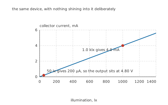
The same device, with nothing shining into it deliberately.
Worked example — As a light sensor
Take the transistor out of the package and point it at a room. At 4.0 µA per lux, a bright 1.0 klx gives 4.0 mA — more than enough to saturate the 1.0 kΩ load.
A dim 50 lx gives 200 µA, leaving the output at 4.80 V.
The response is linear in illumination and the sensitivity is high, which is why the device that makes a poor fast detector makes a good slow one: object counters, tape-end sensors, break-beam detectors and ambient-light switches.
Four things to check before committing
Which output the part has. Transistor output means a transfer ratio and a slow edge. Darlington output means a much larger ratio and a slower edge still. Logic output means a defined threshold and a fast edge, at the cost of needing its own supply on the output side.
Whether the base is brought out. Some parts bring the phototransistor's base to a pin. A resistor from base to emitter there bleeds off leakage and speeds the device up, at the cost of sensitivity — the standard cure for an optocoupler that will not turn off cleanly.
What the output side is referenced to. The point of the part is that the two sides are separate, and it is defeated by a single stray connection: a shared ground on the schematic, a shared supply, or a track passing under the package.
Whether an optocoupler is the right isolator at all. For a slow digital signal it is cheap and hard to beat. For an analogue signal its ratio's drift makes it unattractive without feedback, and for anything fast a magnetic or capacitive isolator is usually the better answer.
Common mistakes
- Driving the LED harder for more output — the transfer ratio peaks near 10 mA. At 50 mA it has fallen to 0.224, worse than the 0.550 at 9.74 mA.
- Designing from a fresh part's transfer ratio — assume the end-of-life worst case instead. Here 0.20 rather than 0.550 turns 5.0 mA of needed output into 25 mA of LED drive.
- Expecting speed — 5.0 µs into 1.0 kΩ is about 70 kHz, and a larger load resistor makes it worse: 11 µs and 31.8 kHz into 2.2 kΩ.
- Sharing anything between the two sides — one common ground, one shared supply or one track under the package defeats the barrier the part exists to provide.
- Quoting an isolation figure from memory — withstand voltage, creepage and working voltage are part-specific, standard-specific and revised. Read them for the part you are fitting.
Frequently asked questions
What is the current transfer ratio?
The output collector current divided by the input LED current, usually quoted as a percentage. It rolls the LED's efficiency, the geometry of the gap and the transistor's sensitivity and gain into one number, and every calculation about the part goes through it. Here 9.74 mA of LED current gives a ratio of 0.550 and so 5.36 mA out.
Why does more LED current not give more output?
Because the transfer ratio peaks. This device peaks at 0.55 near 10 mA; at 1.0 mA it has fallen to 0.0873 and at 50 mA to 0.224. The LED's efficiency drops as it heats and the transistor's gain falls at higher current, so past the peak more drive buys less coupling.
How much design margin does the transfer ratio need?
Enough to cover the whole distribution and the LED's ageing. Designing to 0.20 instead of the 0.550 a fresh part gives — a factor of 0.364 — turns the 5.0 mA needed at the output into 25 mA of LED drive through 152 Ω, which is 2.57 times what a new part would have needed.
Why is a phototransistor so slow?
Because the gain that makes it sensitive also multiplies its capacitance. The load resistor has to charge that multiplied capacitance, so a 1.0 kΩ load gives a 5.0 µs edge and about 70 kHz, while 2.2 kΩ gives 11 µs and 31.8 kHz. A photodiode with an amplifier is the fast alternative.
What isolation voltage can I assume?
None. Withstand voltage, creepage, clearance and working voltage are safety-agency figures tied to a named standard, a specific part and a specific test, and they are revised. This lesson deliberately publishes no such number. Read them from the manufacturer's data for the part you are fitting, and remember the isolation is only as good as the layout around it.