
Quick Answer
A diode can be treated as a perfect switch, as a switch with a fixed voltage drop, as that drop plus a small series resistance, or as the full exponential. Each is a straight line standing in for a curve, exact at one current and wrong elsewhere, and the right choice depends on the supply voltage.
Intuition
Three ways to price a job
Ask a builder what a job will cost and you can get three different answers, all honest. There is the figure scribbled on the back of an envelope, which is quick and might be a quarter out. There is the written quote, which takes an afternoon and is usually close. And there is the final invoice, which is exact and only exists once the work is finished.
Nobody thinks the envelope figure is a lie. It is an estimate whose accuracy matches the decision it is for, which is whether the job is worth thinking about at all. Using the invoice to decide that would be absurd, and using the envelope to sign a contract would be reckless.
A diode gets exactly the same treatment. The full exponential curve is the invoice: correct, and awkward, because no algebra solves a circuit that contains it. Below that sit three progressively cruder models, each of which replaces the curve with a straight line, and each of which is right for a different kind of decision.
The important thing is not which model is best, because none of them is. It is knowing how wrong each one is in the circuit in front of you, so that the answer you get carries an honest error bar rather than a false precision. In some circuits the crudest model of all is within a few percent. In others the second-crudest is out by more than a third. Nothing about the diode tells you which; the supply voltage does.
Practitioner
The four models
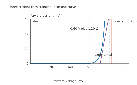
Three straight lines standing in for one curve.
The ideal diode is a switch: no drop forward, no current reverse. It is a vertical line at zero volts.
The constant-drop model adds one number. The diode is a switch in series with a fixed source of 0.70 V, so it is a vertical line shifted to the right. This is the model most circuits get solved with.
The piecewise-linear model adds a second number, a slope. The diode is a fixed source of 0.60 V in series with 1.20 Ω, so it is a sloped line. The two numbers are a fit over a stated range of current, not properties of the part.
The exponential model is the real relation, and it is what everything above is an approximation to.
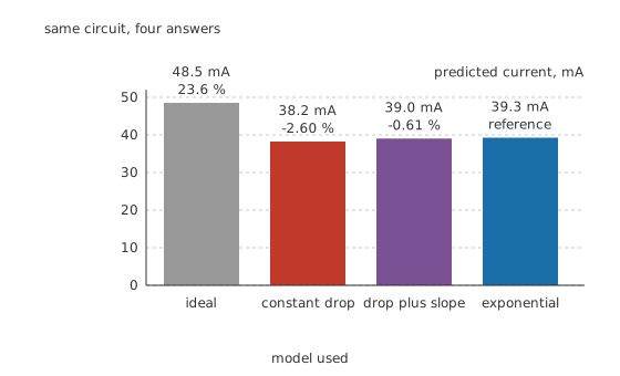
Same circuit, four answers.
Worked example — One circuit, four answers
A 3.30 V rail drives 68 Ω in series with a silicon diode.
The ideal model predicts 48.5 mA, which is 23.6 % high.
The constant-drop model predicts 38.2 mA, which is -2.60 % out.
Adding the slope gives 39.0 mA, or -0.61 %.
The exponential, solved numerically with a saturation current of 1.0 pA and an ideality factor of 1.0 at 300 K, settles at 631 mV across the diode and 39.3 mA through it.
The gap between the last two models is smaller than the tolerance of the resistor. That is the practical verdict on the piecewise model: it earns its extra number in analysis, rarely in design.
Engineer
Where the errors actually live
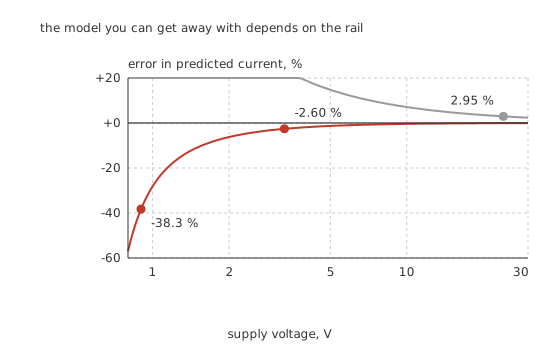
The model you can get away with depends on the rail.
The error in a simple model is not a property of the diode. It is roughly the ratio between the modelling mistake in the drop and the voltage left over to drive the current, so it collapses as the rail rises and explodes as the rail approaches the drop itself.
Worked example — The same models on a rail that cannot afford them
Take the same diode and the same 68 Ω, but run it from 0.90 V.
The constant-drop model now predicts 2.94 mA, because only a fraction of a volt is left after the assumed drop.
The exponential answer is 4.76 mA, because the real drop at that low current is well under 0.70 V.
The model is -38.3 % out, and no amount of care with the arithmetic fixes that.
Worked example — And a rail where the crudest model is defensible
On 24 V through the same resistor, the ideal model predicts 353 mA against a true 342.8 mA.
That is 2.95 %, which is inside a five percent resistor's own tolerance. Pretending the diode is a wire is a perfectly reasonable thing to do here.
Solving the exponential without a simulator
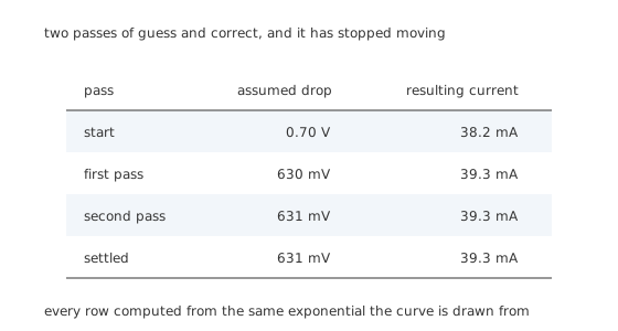
Two passes of guess and correct, and it has stopped moving.
There is no closed form, but there is a two-minute method that always works and converges almost absurdly fast.
Assume a drop, get a current from the rest of the circuit, put that current back into the diode equation to get a better drop, and repeat. Starting from 0.70 V gives 38.2 mA; that current wants 630 mV, which gives 39.3 mA; the next pass gives 631 mV and 39.3 mA, and it has stopped moving.
It converges this fast because the correction runs through a logarithm. A ten percent error in the assumed current is a 2.5 mV error in the drop, and a couple of millivolts on a rail of volts is nothing. The I-V curve lesson's decade rule is the same fact seen from the other side.
Choosing the two numbers of a piecewise fit
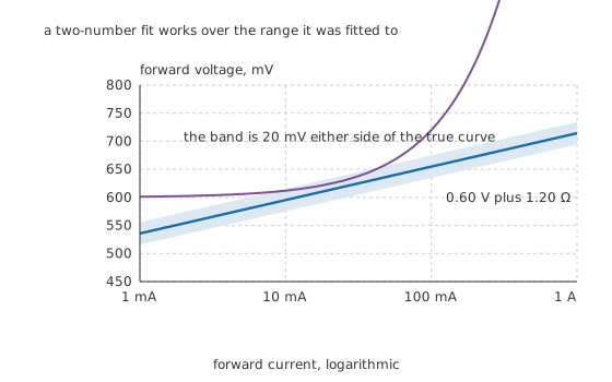
A two-number fit works over the range it was fitted to.
The slope resistance of a piecewise fit is not the diode's small-signal resistance, and confusing the two is a common error. The small-signal resistance is the ideality factor times the thermal voltage, 25.85 mV here, divided by the bias current. At the 39.3 mA operating point above, that true slope is 659 mΩ, well under the 1.20 Ω the fit uses. The fit's slope is a chord across a range of currents; the small-signal resistance is the tangent at one point. They agree at exactly one place and diverge either side of it.
Professional
Which one to reach for, and what none of them do
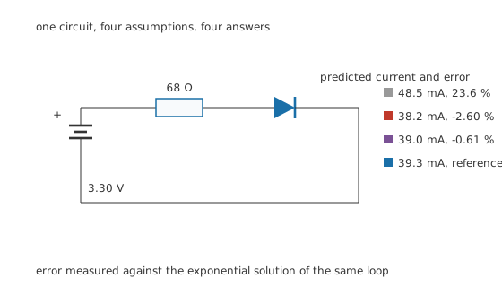
One circuit, four assumptions, four answers.
Use the ideal model for anything above roughly ten volts where you want a feel for the answer, for topology questions such as which diode in a bridge is conducting, and for the first pass of any design. Its error runs the same way every time, so a design that works with an ideal diode and a margin will work with a real one.
Use the constant drop for almost everything else, with the constant chosen for the current the circuit runs at rather than reflexively set to 0.7 V. On a milliamp-scale circuit, 0.6 V is nearer.
Use the piecewise model when you need the drop's variation, which in practice means high-current rectifiers where the resistive part of the drop is a real fraction of the loss, and where the loss is the design question.
Use the exponential where the exponential is the point: log converters, temperature sensing, current mirrors, and anywhere a small voltage change is being turned into a large current change on purpose.
The three things every one of these models is silent about
Time. All four are static relations. A diode that has been conducting holds stored charge that has to be removed before it can block, and none of these models contains that. Schottky diodes exist largely because of it, and a rectifier at high frequency behaves in ways no static model predicts.
Temperature. The models above are all written at 300 K. A real diode's drop falls roughly two millivolts for every degree it warms, so a design validated on a cold bench and run in a hot enclosure sits somewhere else on all four curves.
Breakdown. Every model here describes forward conduction and, at best, a constant reverse leakage. None of them says anything about what happens past the reverse rating, which is where Zener diodes and TVS diodes do their work.
One habit that prevents most model errors
Before choosing a model, compute the ratio between the assumed drop and the voltage available to drive the current. Above about ten, any model will do. Between two and ten, use the constant drop and expect a few percent. Below two, the choice of model dominates the answer and it is worth iterating properly. That one ratio predicts the error curve above better than any rule about part types, and it takes a moment to work out.
Common mistakes
- Using 0.7 V regardless of current — the constant in a constant-drop model should be the drop at the current the circuit actually runs at, which on a milliamp-scale circuit is nearer 0.6 V.
- Trusting a simple model on a low rail — at 0.90 V through 68 Ω the constant-drop model is -38.3 % out, because almost nothing is left over after the assumed drop.
- Confusing a piecewise fit's slope with small-signal resistance — the fit's slope is a chord over a current range, the small-signal resistance is the tangent at one point, and here they differ by nearly a factor of two.
- Adding the piecewise model's second number for accuracy in design — it improves this circuit's answer by under two percent, which is inside the resistor's own tolerance and inside the diode's part-to-part spread.
- Forgetting that all four models are static — none of them describes stored charge, recovery time or capacitance, so none of them predicts anything about a diode at speed.
Frequently asked questions
Which diode model should I use?
Compare the assumed drop with the voltage left over to drive the current. If the rail is more than about ten times the drop, the ideal model is fine. Between two and ten, use a constant drop chosen for the right current. Below that, solve the exponential properly, because the choice of model will dominate the answer.
What is the piecewise-linear diode model?
A fixed voltage source in series with a small resistance, chosen so that the straight line they produce follows the real curve over a stated range of current. The two numbers are a fit, not properties of the part, and quoting them outside the range they were fitted to is where the error comes from.
How do I solve a circuit with a diode by hand?
Guess the drop, work out the current the rest of the circuit gives at that drop, put that current back into the diode equation for a better drop, and repeat. It converges in two passes because the correction runs through a logarithm, which crushes any error in the assumed current down to a few millivolts.
Is the constant-drop model ever badly wrong?
Yes, whenever the supply is close to the drop. At 0.90 V through 68 Ω it underestimates the current by more than a third, because the real drop at that low current is well below the assumed 0.7 V and the difference is a large fraction of what is left.
Why is there no algebraic solution for a diode and a resistor?
Because one relation is a straight line and the other is an exponential, and no rearrangement puts the unknown on one side. The exact solution needs a special function; in practice everyone either iterates, solves numerically, or accepts one of the linear approximations.