
Quick Answer
A photodiode is a junction built so that light reaches its depletion region, where each absorbed photon frees a carrier pair that the junction's own field sweeps out as current. The current is proportional to the optical power over many decades, which makes a photodiode a measuring device rather than merely a detector.
Intuition
The rain gauge
A rain gauge is a cylinder with a scale on it. Twice the rain, twice the reading, and the same instrument works for drizzle and for a downpour without being switched to a different range. What makes it a measuring instrument rather than a wetness detector is that its response is proportional, over a wide range, and stays proportional.
A photodiode is that for light. It is a junction with a window over it, arranged so that light lands where the depletion region is. Every photon absorbed there frees an electron and a hole, and the field that the junction built for itself immediately pulls them in opposite directions and out of the terminals. One photon absorbed, one carrier pair collected, one unit of current.
That one-for-one relationship is why a photodiode is linear, and the linearity is the point. Over six decades of light, twice the light really is twice the current. Nothing needs calibrating for range and nothing bends at the top or the bottom until the detector actually runs out.
It is worth contrasting with the light-dependent resistor, which is the other common light sensor. An LDR's resistance falls as light rises, in a way that is neither linear nor especially repeatable, and it takes hundreds of milliseconds to settle. It is a wetness detector. A photodiode is the gauge.
Practitioner
Responsivity, and where it comes from
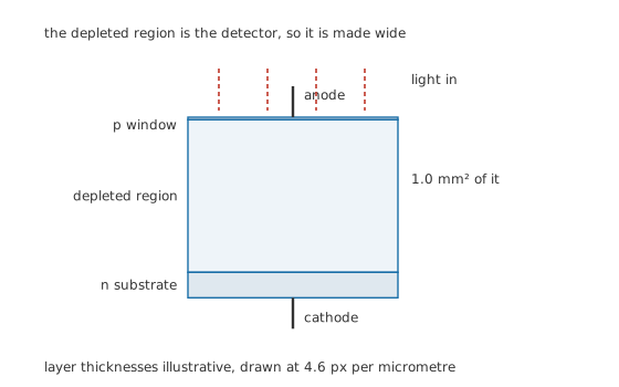
The depleted region is the detector, so it is made wide.
The number on a photodiode's datasheet is its responsivity, in amps per watt.
Responsivity is not an arbitrary constant. It is the quantum efficiency, the fraction of arriving photons that produce a collected carrier pair, divided by the voltage each photon's energy corresponds to.
Worked example — Working out the responsivity, and then using it
At 850 nm a photon's energy corresponds to 1.459 V. With a quantum efficiency of 0.80, the responsivity is 0.548 A/W.
A 1.0 mm² window in an irradiance of 1.0 W/m² collects 1.0 µW of optical power, which gives 548 nA of photocurrent.
Through a 1.0 MΩ transimpedance stage that is 548 mV at the output.
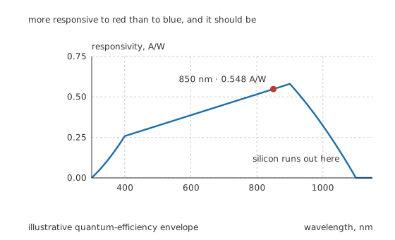
More responsive to red than to blue, and it should be.
Responsivity rises with wavelength, which surprises people who expect a detector to prefer energetic photons. The reason is in the arithmetic above: for the same optical power, longer-wavelength photons are more numerous because each carries less energy, and it is the count that produces current. The curve turns over near 900 nm and dies near 1100 nm because silicon simply stops absorbing photons whose energy is below its bandgap.
The quantum-efficiency envelope behind that curve is an illustrative shape rather than a measured one; the shape of the rise, and the reason for the cut-off, are what generalise.
Engineer
Two modes, and what separates them
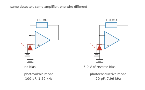
Same detector, same amplifier, one wire different.
Photovoltaic mode leaves the diode unbiased and takes the current out of it into a virtual earth. Photoconductive mode reverse-biases it and does the same. The photocurrent is identical in both; everything that differs comes from the depletion region's width.
Worked example — What the bias buys
Unbiased, this detector's junction capacitance is 100 pF. Into 1.0 MΩ that puts the stage's roll-off at 1.59 kHz.
At 5.0 V of reverse bias the depletion region widens, the capacitance falls to 20 pF, and the roll-off moves to 7.96 kHz, a factor of 5.00.
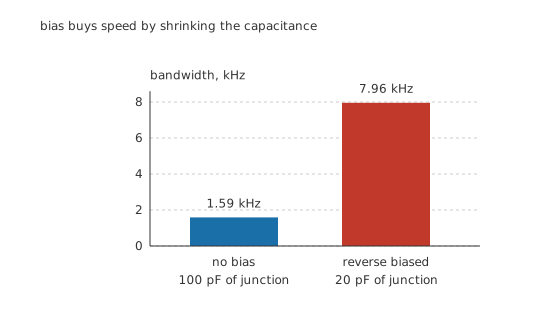
Bias buys speed by shrinking the capacitance.
The cost is dark current. A reverse-biased junction leaks, that leakage is indistinguishable from photocurrent, and it doubles for every ten degrees. So the rule is simple: bias it if you need speed, leave it unbiased if you need to measure very small light levels. Precision light measurement is almost always done unbiased and slowly.
The mode nobody should use for measurement
Left open-circuit, a photodiode produces a voltage rather than a current, and that voltage is not proportional to anything useful.
Worked example — Why open-circuit voltage is the wrong output
The photocurrent forward-biases the diode's own junction until the forward current matches it, so the open-circuit voltage is logarithmic in the light.
At 548 nA against a 1.0 nA saturation current, that is 163 mV.
The relation runs through the thermal voltage, 25.85 mV at 300 K. Drop the light to 1.0 nW, giving 548 pA, and the voltage only falls to 11.3 mV. Three decades of light became a factor of fourteen in voltage.
Logarithmic compression is occasionally exactly what you want, and a solar cell is this mode used deliberately. For measurement it throws away the property the detector was chosen for, and the fix is to hold the diode at zero volts with a transimpedance amplifier rather than letting its voltage move.
Professional
Where the range ends, and what to watch
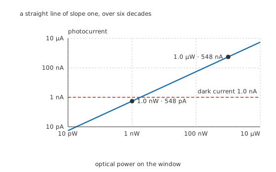
A straight line of slope one, over six decades.
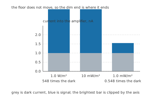
The floor does not move, so the dim end is where it ends.
Worked example — Where the detector runs out
At 1.0 W/m² the photocurrent is 548 nA, which is 548 times the 1.0 nA dark current. Comfortable.
At 1.0 mW/m², a thousand times dimmer, the photocurrent is 548 pA, which is only 0.548 of the dark current.
The detector has not become non-linear. It has run into a constant offset it cannot distinguish from signal, and no amount of gain separates them.
Dark current is an offset, not noise, so it can be subtracted. Measure it with the light blocked and take it away. What cannot be subtracted is its shot noise and its drift with temperature, and those set the real floor.
Four things that decide a real design
The transimpedance resistor sets gain and bandwidth together, and they fight. Doubling 1.0 MΩ doubles the output for a given light and halves the bandwidth, because the same stray capacitance now sits across twice the resistance. A photodiode circuit that is not fast enough usually cannot be fixed by changing the diode.
Capacitance at the summing node also causes instability, not just roll-off. The detector's capacitance and the feedback resistor form a phase lag inside the amplifier's loop, and a transimpedance stage with a large detector and a high-value resistor will ring or oscillate without a small capacitor across the feedback resistor. That capacitor is not optional and it is the first thing to check on a misbehaving stage.
Ambient light is a signal too. A detector cannot tell your light from the room's, and daylight through a window is enormous compared with most signals. The answer is almost never a filter alone; it is to modulate the source and detect only the modulation, which is what IR emitters and photointerrupters do.
Match the detector's area to the job. A larger window collects more light in direct proportion, so it improves the signal, but its capacitance grows in proportion too, so it costs bandwidth in exact proportion as well. That trade is close to one for one, which means area is a decision rather than an improvement.
Related devices, and the one thing they change
A phototransistor is a photodiode with a transistor's gain built in. It gives far more current for the same light, which makes it easy to use, and it gives away the linearity and the speed. It is a detector rather than a gauge.
A PIN photodiode is the structure drawn in this lesson: an undoped layer deliberately inserted to make the depletion region wide. That is a photodiode optimised in the direction this lesson has assumed throughout, and it is what most real parts are.
An avalanche photodiode runs near breakdown so that each freed pair triggers more, giving internal gain at the cost of noise, a high bias voltage and strong temperature sensitivity. It is what you reach for when the signal is genuinely at the floor.
Common mistakes
- Using the open-circuit voltage as the output — it is logarithmic, so a thousandfold change in light becomes a factor of fourteen in voltage, and the linearity the detector was chosen for is thrown away.
- Expecting a photodiode to respond better to blue than to red — responsivity rises with wavelength, because the same power in longer-wavelength photons means more photons and therefore more carriers.
- Forgetting the compensation capacitor across the feedback resistor — the detector's capacitance inside the amplifier's loop will make a high-gain transimpedance stage ring or oscillate.
- Treating dark current as noise — it is a stable offset that can be measured and subtracted; what limits the floor is its shot noise and its drift with temperature.
- Reverse-biasing a detector that needs to measure very small signals — the bias buys bandwidth and pays for it in dark current, which is exactly the wrong trade at the bottom of the range.
Frequently asked questions
How does a photodiode work?
Light absorbed in the junction's depletion region frees electron-hole pairs, and the field already present there sweeps them apart and out of the terminals before they can recombine. The result is a reverse current proportional to the number of photons absorbed, which is proportional to the optical power.
What is responsivity?
The photocurrent produced per watt of incident optical power, in amps per watt. It is the quantum efficiency divided by the photon energy expressed as a voltage, so it depends on wavelength: at 850 nm with 0.80 quantum efficiency it works out at 0.548 A/W.
Should I reverse-bias a photodiode?
Bias it if you need speed. Reverse bias widens the depletion region, which cuts the junction capacitance and raises the bandwidth, here by a factor of five. Leave it unbiased if you need to measure very small light levels, because the bias also raises the dark current that sets the floor.
Why does the responsivity fall above about 900 nm?
Because silicon stops absorbing. A photon whose energy is below the bandgap cannot free a carrier pair, so it passes through. The cut-off near 1100 nm is silicon's band edge, and detectors for longer wavelengths use different materials entirely.
What limits how little light a photodiode can measure?
The dark current and its noise. The dark current itself is a stable offset that can be measured with the light blocked and subtracted, but its shot noise and its drift with temperature cannot be. On the detector here the signal falls below the dark current at about a milliwatt per square metre.