
Quick Answer
A light-dependent resistor is a resistor whose resistance drops as the light falling on it rises. The relationship is a power law rather than a straight line, so resistance against illuminance is straight only on logarithmic axes. The cell is also slow, taking tens or hundreds of milliseconds to settle after the light changes.
Intuition
A resistor that watches the room
Walk out of a lit kitchen into the garden at dusk and the world dims, but nowhere near as much as it should. The kitchen might sit at a few hundred lux and the garden at one or two, a hundredfold drop, and what you notice is something far gentler than that. Whatever the mechanism, the impression is compressed against the physical quantity.
A light-dependent resistor does something with the same flavour. It is a two-terminal part with no polarity: a serpentine track of light-sensitive material laid between two electrodes, behind a window. Light reaching that track lowers its resistance. The resistor you already know holds one value whatever happens to it; this one holds whatever the light says.
Cover it and it climbs to 1.20 MΩ. Give it the light of a dim room at 1.00 lux and it settles near 43.0 kΩ. Under ordinary indoor working light of 200 lux it falls to 949 Ω. Those three figures span more than three decades of resistance, and that span is the reason the part exists: very little else this cheap reports light across that kind of range without an amplifier standing behind it.
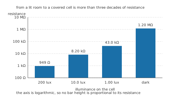
The axis is logarithmic, so bar heights compare exponents rather than ohms.
The span is generous but it is not well behaved. The resistance does not track light in proportion, and the cell does not answer at once.
Practitioner
Reading the cell with a divider
Plot resistance against light on ordinary axes and you get a curve that tells you very little. Take the logarithm of both and it straightens into a line, which is the signature of a power law: multiply the light by some factor and the resistance divides by a fixed factor of its own.
The exponent that sets the second factor belongs to the individual cell and to the material it is made from. Everything here is computed from 0.72 as this lesson's illustrative exponent, together with one reference point, 8.20 kΩ at 10.0 lux. A tenfold change in illuminance then divides the resistance by 5.25 rather than by ten. That shortfall is the compression, and it is why a cell whose resistance covers three decades is watching light over rather more than four.
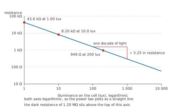
The slope triangle is drawn on the line itself, so the exponent is measured off the plot rather than asserted underneath it.
No circuit reads a resistance directly, so the cell almost always goes into a voltage divider and the rest of the design reads a voltage instead.
Put the cell on top and the fixed partner below, and the output climbs with light. Swap them and it falls with light. Neither is more correct; pick whichever gives the comparator or converter downstream the polarity it wants.
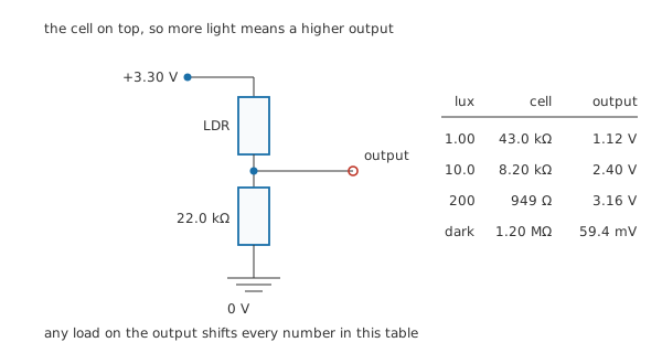
The output terminal is drawn open, because a load on it changes every voltage in the table.
Across that range the junction moves from 1.12 V at the dim end to 3.16 V under working light, and collapses to 59.4 mV once the cell is covered. Note how unevenly those are spaced: the two brightest readings are closer together than the dimmest pair, which is the compression showing up as voltage.
Worked example — The divider at the reference point
The cell at 8.20 kΩ sits above a partner of 22.0 kΩ across 3.30 V, which puts the output at 2.40 V.
The chain draws 109 µA. That leaves 0.896 V across the cell and 97.9 µW dissipated in it.
That last number is worth a second look even though it is tiny. A cell warmed by its own dissipation drifts, and drift on a light sensor reads as a light level that is not there. Keeping the chain current small costs nothing here, and it is worth doing deliberately rather than by accident.
One caution about the light figures themselves. Lux is weighted for human vision, and the cell's own sensitivity varies with wavelength in a way that owes nothing to how a human eye is built. A resistance quoted at a stated illuminance therefore pins nothing down unless the light source is stated too, which is why the same cell reads differently under daylight, an incandescent lamp and a white LED at the same meter reading.
Engineer
The slope, and what it costs
A compressed characteristic is a gift at one end of the range and a nuisance at the other. Four decades of light stay inside one rail's worth of volts, so nothing clips and nothing needs ranging. What you give up is resolution near the bright end, where the curve has flattened and a large change in light barely shifts the output.
Put a comparator on that output and the cost turns into a number. Suppose the circuit should switch at 20.0 lux. The cell there is 4.98 kΩ, so the divider gives 2.69 V and that is the trip level. Now give the comparator hysteresis of 3.00 % either side, a modest amount chosen here to make the arithmetic concrete: the window runs from 2.61 V to 2.77 V.
Invert the divider at each edge, then invert the power law, and that narrow band of volts turns out to cover 16.1 lux to 25.4 lux of light, a ratio of 1.57. The light has to rise by more than half again before the circuit changes its mind.
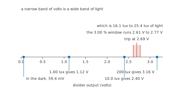
The hysteresis band is drawn at true width on the same axis as the readings, which is what makes the light figures beside it surprising.
Usually that is exactly what you want. A streetlight controller with a sharp threshold hunts at dusk, because passing clouds and its own lamp both move the reading across the trip point. The compression means a little electrical hysteresis buys a lot of optical hysteresis, and the design gets stable switching almost by accident. It also means the switching point is a light band — not a light level — and any specification that names one number is describing the middle of that band.
The cell takes its time
Speed is the other limitation, and for most designs it is the bigger one. A photoconductive cell has to build up and then clear its population of free carriers, and neither happens instantly. Worse for a designer, the two directions do not take the same time.
Towards light the cell settles with a constant of about 35 ms. Towards dark, about 180 ms — longer by a factor of 5.14. Both figures are illustrative and used here only to make the asymmetry arithmetic; the real ones depend on the part, on the two light levels it is moving between and on temperature. Taking three constants as the working definition of settled puts 105 ms on one direction and 540 ms on the other.
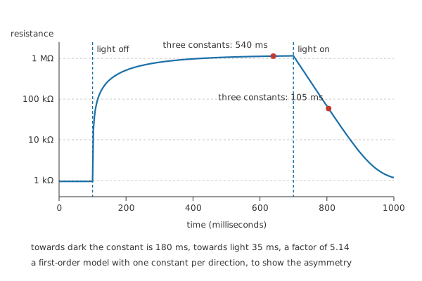
A first-order model with one constant per direction, drawn to show the asymmetry rather than to predict a particular cell.
Some of that slowness is useful. A mains-lit room flickers at twice the supply frequency and the cell averages straight through it, so an LDR-based light switch needs no filtering to ignore the flicker that would confuse a fast photodiode. The trouble starts when something downstream expects an answer inside a video frame, or when a light meter is swept across a scene and reports the previous part of it.
Professional
Choosing the partner, and what the cell will not tell you
The partner resistance does two jobs at once. It decides where the threshold lands on the light scale, and it decides how much of the supply the output actually moves across the range you care about. Those two pull in different directions often enough to be worth checking.
Over a working range from 1.00 lux to 200 lux the cell runs between 43.0 kΩ and 949 Ω, and the swing is largest when the partner sits at the geometric mean of those two resistances, 6.39 kΩ. That choice returns 2.45 V of output. The 22.0 kΩ used everywhere above returns 2.05 V — less, but it was chosen anyway because it puts the interesting part of the light range in the middle of the output span. The peak is broad, so both are workable and the threshold argument wins.
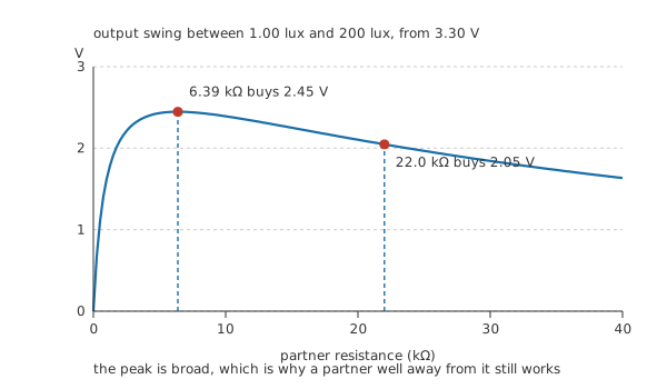
The curve is the swing between the two ends of the working range, so a partner far from the peak costs surprisingly little.
A capacitor across the partner is the usual next addition, for supply noise rather than for the light. At the reference point the two arms in parallel present 5.97 kΩ to that capacitor, so 1.00 µF gives a time constant of 5.97 ms.
Set that against the cell's own 180 ms and the filter is nowhere near being the slow element. Knowing which part of a slow circuit is the slow part saves a lot of component swapping, and the same habit is worth carrying into every RC timing question.
Four things to settle before committing to one, in roughly the order they cause trouble.
Absolute accuracy is not on offer. Cell-to-cell spread at a stated illuminance is wide, wider than the tolerance bands you would accept on a fixed resistor, so designs that need a calibrated light level either calibrate each unit or use a different sensor. Threshold and ratio work is where the part is comfortable.
Its recent history matters. A cell moved from bright light to dim settles towards a slightly different value than the same cell arriving from darkness, and it can take much longer than the constants above to finish. A resistance quoted for a cell is only meaningful alongside the light history it was measured after.
Temperature moves the characteristic, and it moves it more at low light than at high. A cell used near a threshold outdoors is a cell whose threshold drifts with the season.
The classic cell's sensing layer is a cadmium compound. Cadmium is restricted in electrical and electronic equipment in several markets, which is the practical reason new designs so often reach for a photodiode or a phototransistor instead, along with the speed and the calibration those parts bring. Existing LDR designs, hobby work and equipment outside the scope of those rules carry on using them, and the part remains one of the easiest introductions to sensing anything at all.
A thermistor is the same idea pointed at temperature: a resistance that reports an external variable through a nonlinear law and needs a divider to become a voltage. The laws differ, and so does the linearisation each one wants, but the circuit around them is the same circuit, and a reader comfortable with one will find the other short work.
Common mistakes
- Treating the cell as linear — resistance against illuminance is a power law, so doubling the light does not halve anything. Work in logarithms or work from computed points; do not interpolate on a linear scale.
- Reusing a lux figure across light sources — the cell's response varies with wavelength, so a resistance measured under an incandescent lamp does not carry over to a white LED at the same meter reading.
- Expecting a fast answer — the cell needs tens to hundreds of milliseconds to settle, and it is slower going dark than going light. Anything that samples faster than that is reading history.
- Loading the divider output — a comparator or a converter input is fine, but any load drawing real current sits in parallel with the partner and moves every voltage the design was built around.
- Setting a threshold with no hysteresis — a bare comparator on a slow, noisy light signal chatters at dusk, and adding hysteresis costs one resistor.
Frequently asked questions
What does an LDR actually do?
Its resistance falls when light reaches the sensing layer between its two terminals. There is no polarity and no junction, so it works on AC as readily as DC, and the usual circuit puts it in a divider so the change appears as a voltage.
Why does resistance not fall in proportion to the light?
Because the physics gives a power law with an exponent below one rather than a straight-line relationship. One decade of extra light divides the resistance by around five in the illustrative cell used here, not by ten, which is why the plot is straight only on logarithmic axes.
Should the LDR go on the top or the bottom of the divider?
Either. On top, the output rises with light; underneath, it falls with light. Choose whichever polarity suits the comparator or converter that reads it, and remember that the two arrangements do not have mirror-image curves because the cell is not linear.
Can an LDR measure light, or only detect it?
It detects reliably and measures poorly. Part-to-part spread, the dependence on the light source's spectrum, temperature drift and the cell's memory of recent exposure all sit between a resistance and a number of lux. For thresholds and relative changes it is entirely adequate.
Why do new designs often use a photodiode instead?
Speed, a better defined spectral response and easier calibration, plus the cadmium restriction that applies to the classic cell in several markets. A photodiode needs an amplifier where an LDR needs one fixed resistor, which is the trade being made.