
Quick Answer
An infrared emitter and a photodetector make a sensor by pointing at each other and noticing when something interrupts the path. Ordinary room light in the same band is larger than the signal, so practical links switch the emitter at tens of kilohertz and build a receiver that responds only to that rate.
Intuition
The mark only the machine can see
A banknote has marks printed on it in ink that does nothing at all under ordinary light. Put it under the right lamp and the marks appear, bright and obvious, in a place your eye had reported as blank. Nothing was hidden. Your eye simply does not respond in that part of the spectrum, and the machine at the till does.
An infrared emitter and detector pair works on that arrangement. The emitter is a light-emitting diode built from a material whose bandgap is small enough that its light lands past the red end of what you can see, and the detector is a silicon photodiode that happens to be most responsive right there. The two of them hold a bright conversation across a gap that looks, to you, entirely empty.
That is the whole sensor. Point them at each other, watch the detector's current, and anything that passes between them announces itself by cutting the current off. A printer counting sheets, a lift door refusing to close on someone's arm, a mouse wheel counting its own rotations — the same pair of parts, arranged for a different thing to interrupt them.
The trouble is that the room is not empty of infrared either. Daylight and filament lamps put out a great deal of it, and the detector cannot tell whose photons it just absorbed. That problem, and its cure, is most of what this lesson is about.
Practitioner
Where the light goes, and how much of it arrives
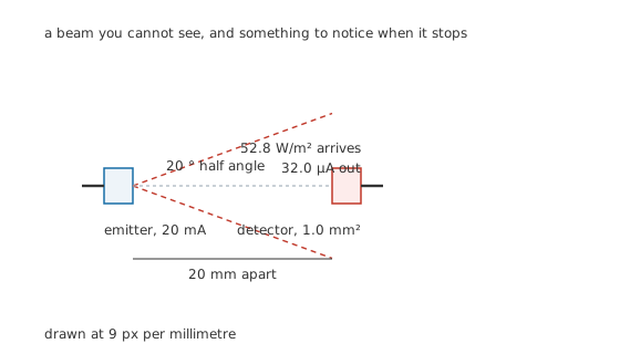
Drawn to one scale, because the geometry is the sensor.
An emitter is specified two ways at once. It has an electrical side, where 20 mA through 1.40 V is 28 mW of dissipation, and it has an optical side, where 8.0 mW of that leaves as radiation. The ratio, 28.6 %, is far better than a visible LED manages, and the reason is simply that the forward voltage sits closer to the photon voltage when the photon is a low-energy one.
At 940 nm that photon voltage is 1.319 V, so the emitter's 1.40 V leaves only 81 mV of overhead. Everything above the photon voltage is heat, and there is very little of it here.
The optical power does not go everywhere. It leaves in a cone, and the package's lens sets how tight that cone is. A 20 ° half angle is 0.379 sr of solid angle, which turns 8.0 mW into 21.1 mW/sr of radiant intensity — and radiant intensity, unlike power, is the quantity that survives the trip.
The detector end is the photodiode relation, with its responsivity worked out at this wavelength rather than borrowed from another one.
Worked example — From the emitter's rating to the detector's current
The emitter puts 8.0 mW into 0.379 sr, which is 21.1 mW/sr.
At 20 mm that intensity spreads over the square of the distance, giving 52.8 W/m² of irradiance at the detector.
A 1.0 mm² window in that irradiance collects 52.8 µW of optical power.
With a quantum efficiency of 0.80, the responsivity at this wavelength is 0.607 A/W, so the detector delivers 32.0 µA.
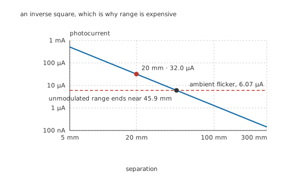
Double the distance, quarter the signal. It compounds quickly.
The inverse square is the hard constraint in this whole family of sensors. Nothing in the electronics changes it, because it is not electrical.
Engineer
Two arrangements, and one shared enemy
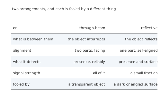
Convenience on one side, reliability on the other.
There are two ways to arrange the pair, and choosing between them is usually a mechanical decision rather than an electrical one. In a through-beam sensor the emitter faces the detector across the gap and the object interrupts the path; the detector gets the whole beam or none of it, and the margin is enormous. In a reflective sensor both parts sit in one package facing the same way, and the object has to bounce some fraction back. That fraction is small, and it depends on the object's colour and its angle, which is why a reflective sensor that works beautifully on white card can go blind on matt black.
Either way the same enemy is waiting.
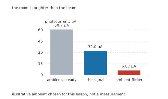
The room is brighter than the beam, and it is not close.
Take an illustrative 100 W/m² of ambient light in the detector's band — a bright room, not direct sun. Across the same 1.0 mm² window that is 100 µW and therefore 60.7 µA, which is 1.89 times the signal you were trying to measure. A detector that simply watches its own current sees the room, with the beam as a small ripple on top.
Worse, the room does not hold still. Artificial lighting fed from the mains flickers at 100 Hz, twice the supply frequency, and even a modest 10 % depth of that is 6.07 µA of moving interference. That is a fifth of the signal, and it moves, so no fixed threshold escapes it.
Which sets the range of a plain unmodulated detector precisely. The signal falls as the square of distance while the flicker does not fall at all, so the two meet at 45.9 mm and past that the sensor is reporting the lighting.
Professional
Modulation, and why every remote control does it
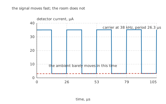
The signal moves fast; the room does not.
The cure is to stop asking how much light is there and start asking is there light changing at my rate. Switch the emitter on and off at 38 kHz, a period of 26.3 µs, and build a receiver that responds only near that frequency. The ambient is now irrelevant — not filtered out afterwards, but never admitted. Its steady part is blocked by a capacitor, and its 100 Hz flicker is 380 times too slow to get through the band-pass.
This is why every infrared remote control in the house works the same way, and why they mostly interoperate badly but coexist fine. A receiver module contains the photodiode, an amplifier, a band-pass filter and a demodulator in one three-pin package, and it reports only whether a burst of carrier is present. A burst of 600 µs holds 22.8 cycles, which is ample for the filter to settle and decide.
Modulation also lets you spend current where it does something. Because the emitter is off most of the time, it can be driven far harder during its on time than its continuous rating would allow, and average dissipation stays low. That matters, because range is expensive.
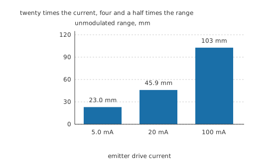
Twenty times the current for four and a half times the range.
Range grows only as the square root of drive current, because the light falls as the square of distance. Going from 5.0 mA to 100 mA — twenty times the current, and twenty times the emitter's dissipation — moves the limit from 23.0 mm to 103 mm. That is a poor trade, and it is why the useful gains come from somewhere else: a tighter lens to concentrate the same power into less solid angle, a larger detector area, and above all a receiver that is not fighting the room.
One practical warning about the invisibility. An infrared emitter looks dead when it is working, so the ordinary check of glancing at it tells you nothing. Point a phone camera at it instead — most phone sensors respond well past the visible, and a working emitter shows up on the screen as a pale violet glow. It is the same trick as the lamp at the till: the mark was always there, and you needed the right eye.
Common mistakes
- Deciding an emitter is dead because it looks dead — it emits nothing you can see, working or not. Point a phone camera at it instead; most phone sensors respond past the visible and show a working emitter as a pale violet glow.
- Setting a fixed current threshold against bench lighting — the room's contribution can exceed the whole signal, and it moves at twice the mains frequency. Measure the detector's current with the emitter off, in the worst lighting the product will meet, before choosing anything.
- Reaching for more drive current when the range falls short — range grows only as the square root of drive, so it is the most expensive lever available. A tighter lens concentrates the same radiant power into less solid angle and costs nothing to run.
- Assuming a reflective sensor that works on white card works on anything — it depends on the object to return some fraction of the beam, and matt black at an angle returns almost none. If the object varies, a through-beam arrangement removes the variable.
- Treating a receiver module as a light meter — it reports whether a burst of carrier is present, not how much light there is. Pointing it at a steady infrared source gets you nothing at all, which is the entire point of it.
Frequently asked questions
Why are infrared links modulated instead of just switched on and off?
Because ambient light in the same band is usually larger than the signal. In the arrangement here the room contributes 60.7 µA against a 32.0 µA signal, and even its flicker alone is 6.07 µA. Switching the emitter at 38 kHz and filtering for that rate rejects the room rather than fighting it.
Why 38 kHz in particular?
It is high enough to be far above anything the lighting does — 380 times the 100 Hz flicker here — and low enough that cheap receivers and ordinary emitters handle it comfortably. It became the common choice for consumer remote controls, which is why receiver modules are inexpensive at that frequency.
What sets the range of an infrared sensor?
The inverse square, mostly. Irradiance falls as the square of distance while the interference does not, so an unmodulated pair here runs out near 45.9 mm. Range is bought with a tighter lens, a larger detector and a modulated receiver, and only very inefficiently with drive current.
Why is an infrared emitter more efficient than a visible one?
Its forward voltage sits closer to the photon voltage. At 940 nm a photon corresponds to 1.319 V and the emitter runs at 1.40 V, leaving 81 mV of overhead to become heat. A visible emitter needs a wider bandgap, a higher forward voltage, and the extra volts do not turn into light.
Through-beam or reflective?
Through-beam whenever the mechanics allow it. The detector receives the whole beam or none of it, so the margin is large and the object's colour is irrelevant. A reflective sensor is chosen when only one side of the object is reachable, and it must then be tested on the least cooperative surface it will meet.