
Quick Answer
A current divider is a parallel pair of branches that splits a known total current between them in inverse proportion to their resistances. Each branch's share is the total multiplied by the other branch's resistance over the sum of both, so the lower resistance carries the larger current.
Intuition
The smaller resistance takes the bigger share
Current arriving at a point where two components offer separate routes back to the same place travels along both of them. How much goes each way is settled by how readily each route conducts, so the branch with the lower resistance ends up with more of the total.
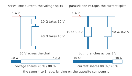
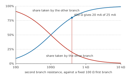
Send 1 A into a pair of branches, one of 10 Ω and one of 40 Ω. The smaller resistance takes 0.8 A and the larger takes 0.2 A, four times as much going down the branch that conducts four times as well. Add the two and the total you started with comes back, since nothing else leaves the junction.
How those two numbers were produced is where the arrangement catches people out. The share belonging to the 10 Ω branch was worked out from the 40 Ω sitting in the other branch: the total, scaled by the opposite resistance over the sum of the pair. Every instinct says a branch's own resistance ought to fix its own current, and it does, provided you already know the voltage standing across the pair. Start from the total current instead and the roles trade places, so the resistance that goes on top is the one belonging to the branch you are not asking about.
A voltage divider runs the other way round. In a series chain a component's share of the voltage grows with its own resistance, while in a parallel pair a branch's share of the current shrinks as its own resistance grows. Whichever quantity is common to everything decides which resistance ends up in the numerator, and setting the two arrangements against each other is the quickest way to keep them apart.
Practitioner
Working the split out from the total
Everything the answer needs is already true of any parallel pair. The branches share one voltage, because they connect the same two points, and the currents leaving through them account for the whole of what arrived, which is Kirchhoff's current law at the junction the branches hang from. Between them those constraints settle the split without the voltage ever having to be found.
The subscripts repay reading slowly, because that is where the trap sits. I_1 is the current in the branch whose resistance is R_1, and R_2 — the resistance of the other branch — is what sits on top. Since the denominator is symmetric, that numerator is the only asymmetry anywhere in the expression, and the second branch comes from the same line with the two labels exchanged.
Those two serve as a check rather than as the method. The pair's combined resistance turns the total current back into a node voltage, and Ohm's law on either branch then has to agree with what the divider said.
Worked example — Checking one split two ways
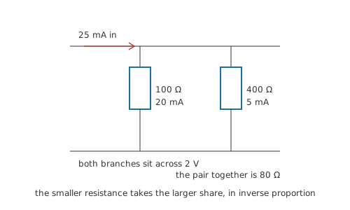
A total of 25 mA arrives at a junction and leaves through two resistors that both return to the same second junction. One is 100 Ω; the other is 400 Ω.
Take the branch through the smaller resistor. Its current is the total scaled by the other branch's resistance over the sum of the two: I_1 = I_T × R_2 ⁄ (R_1 + R_2) = 20 mA. Exchange the labels and the second branch works out at 5 mA, and the two add back to what arrived.
The long route arrives at the same place. Combined, the pair is R_p = 80 Ω, so the voltage standing across both branches is I_T × R_p = 2 V. Ohm's law on the first branch, V ⁄ R_1, returns 20 mA a second time.
Put the wrong resistance on top — each branch weighted by itself — and the first branch comes out at 5 mA, which is the current in the other branch: a plausible figure of the right size, attached to the wrong resistor. Wrong answers of that shape look entirely reasonable on their own, and only the cross-check above tells them apart.
Reaching for the divider at all depends on what you already hold. Its input is a total current, and a total current is the unusual thing to have. Most sources hold a voltage, and where the node voltage is available each branch takes one division and needs nothing beyond Ohm's law. The divider comes into its own when the total is what was given or measured: the output of a current source, the source current in a Norton equivalent, a supply current read off a meter during fault-finding, or a branch current already established while reducing a series-parallel network.
Engineer
Both branches sit at one voltage
Call that voltage V. Branch one carries V ⁄ R_1 and branch two carries V ⁄ R_2, and since these are the only routes out, I_T = V ⁄ R_1 + V ⁄ R_2. Solve for V and it is I_T multiplied by the parallel combination, R_p = R_1 R_2 ⁄ (R_1 + R_2). Substitute that into I_1 = V ⁄ R_1: the R_1 underneath cancels the R_1 in the product above it, and what is left is I_1 = I_T × R_2 ⁄ (R_1 + R_2).
So the opposite resistance is the factor of R_p that survives the cancellation, rather than an oddity to be memorised. R_p carries both resistances multiplied together, and converting the voltage back into a branch current divides by that branch's own resistance, which removes one of the pair and leaves the other standing in the numerator.
Rewrite the same argument in conductance and the strangeness disappears.
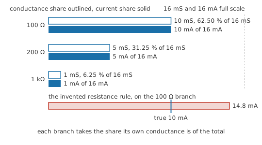
Each branch carries I_k = V × G_k, and V is common to all of them, so I_1 ⁄ I_T = G_1 ⁄ (G_1 + G_2). A branch's own conductance is on top, exactly where intuition wanted it, and the statement extends to any number of branches: each takes a share of the total in proportion to its own conductance, over the sum of every branch conductance present. No closed-form resistance version of that exists for three branches or more. Putting "the sum of the other resistances over the sum of all of them" on top is an invention rather than an extension, because a ratio of conductances only rearranges into a tidy ratio of resistances when there are exactly two of them to rearrange.
The numbers show how wide the gap is. Take branches of 100 Ω, 200 Ω and 1 kΩ with 16 mA arriving. Their conductances are 10 mS, 5 mS and 1 mS, summing to 16 mS and presenting a combined 62.5 Ω to whatever is driving them. Each branch then takes the total in proportion to its own term: 10 mA, 5 mA and 1 mA, adding back to what arrived. The invented three-branch rule would have handed the first branch 14.8 mA, a current that branch never carries.
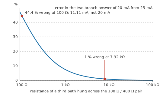
Once the algebra is finished it becomes easy to lose sight of what the result depends on. The total has to be the real total: anything else drawing from either junction — a third resistor, a load hung on the tap, a meter with finite input resistance, leakage across a dirty board — is one more term in the conductance sum, and the two-branch form has no room for it. That is the same defect that spoils a loaded voltage divider, arriving from the other side.
Each branch also has to run between the same pair of junctions, and the copper between them belongs to whichever branch it sits in. A length of wire in series with one adds its resistance to that branch's total, so where the branch resistances are themselves small, wire and connector resistance can move the split further than the components do.
And the expression only accepts constants. A lamp, a semiconductor junction, a thermistor or a switching device has no fixed R to offer it, and parallel branches of that kind redistribute current between themselves as they warm instead of holding a ratio.
Linearity in the total is one thing the derivation does guarantee: double I_T and both branch currents double, while the ratio between them stays put. The split belongs to the resistances alone, fixed as soon as they are chosen and indifferent to the size of whatever arrives.
Professional
Meter shunts and shared sense resistors
Extending a meter's range
A moving-coil instrument is the most literal current divider there is: the movement is one branch, a shunt is the other, and the design problem is to size the shunt so the movement receives a fixed fraction of whatever passes through the pair.
Worked example — Putting a 1 A range on a 1 mA movement
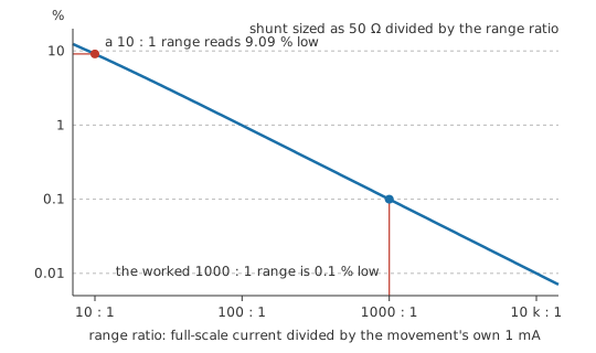
The movement deflects fully at 1 mA and its coil measures 50 Ω. Full-scale indication is wanted at 1 A through the pair, so the shunt has to carry everything the movement does not, which is 0.999 A.
Both branches stand at one voltage, and that turns the design into a division rather than a proportion: R_shunt = R_move × I_fsd ⁄ I_shunt = 50.05 mΩ. At full scale the shunt drops 50 mV, which is what the instrument inserts into the circuit under test.
The awkward figure is real, and it comes from the movement itself. Its own current is part of the total, so the shunt is never quite the resistance the range ratio on its own suggests. Fit a round 50 mΩ instead and the movement reaches only 0.999 mA while 1 A is flowing, an indication 0.1 % low. On a range this wide that sits below the movement's own grade of accuracy, though on a range of ten to one the same shortcut would show.
Digital instruments have no coil to protect, and they keep the shunt anyway, along with everything that follows from it. The drop across it is the meter's burden voltage — in series with whatever is being measured, and reducing the very current the meter was brought in to read — so meter loading is as real on current ranges as on voltage ranges. Shunts are therefore specified for a small round full-scale drop, a few tens of millivolts. A shunt small enough for that is a resistance of milliohms, at which point its own joints and leads come to a comparable resistance, and four-terminal current-sense resistors with separate sensing tabs exist to keep the two apart.
Sharing a current between two parts
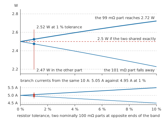
When two resistors share a current the split follows their conductances precisely, and tolerance sets the limit on how equal it can be made. Two nominally 100 mΩ sense resistors of 1 % tolerance may sit at opposite ends of their band, 99 mΩ against 101 mΩ. Feed the pair 10 A and the divider gives 5.05 A in the lower-valued part against 4.95 A in the higher, dissipating 2.52 W and 2.47 W respectively. Each part is still within its own tolerance of an equal share. To a first approximation that imbalance equals the tolerance whatever the nominal value happens to be, which makes the derating sum the same at any resistance: size every part in the group for the share the worst-case unit takes.
Two resistors stay stable together because neither one's value depends on how much current it took. Paralleled semiconductor devices offer no such guarantee, since a forward voltage that falls as the junction warms turns a small initial imbalance into a growing one, and parallel circuits works that case through.
The scarcity of known currents
Voltage dividers are everywhere and current dividers are not, and the reason lies in what real sources provide. Batteries, regulators and supply rails hold a voltage and let the load settle the current, so in a parallel group the node voltage is normally the quantity available first. From there, Ohm's law on each branch is a shorter route than the divider. What is left over for the divider is the narrower set of cases where a current is the given: the output of a current mirror or other current source; a Norton equivalent produced part-way through an analysis; a measured supply current being apportioned during fault-finding; a paralleled sense or ballast network whose total is set elsewhere; and the meter shunt, whose only job is to divide a current.
Safety
Both the shunt and the ten-amp sharing example above stop at the arithmetic; neither was wired up and neither was put in front of a meter. A shunt in a high-current path drops only millivolts, and that small reading is a fact about the shunt rather than about the source behind it, which may be able to push hundreds of amperes into a fault. A multimeter on a current range is a low resistance by design and becomes a short circuit if it is placed across a source instead of in series with a load; the working practices are in measuring V, I and R and electrical safety fundamentals.
Common mistakes
- "My branch is R_1, so R_1 belongs on top" — the numerator is the resistance of the branch you are not solving for. What comes out is the current in the other branch, a plausible figure of the right magnitude that survives every rough sanity check.
- Extending the two-branch form to three or more branches by putting the sum of the other resistances on top. There is no such rule. Convert to conductances, or reduce the network two branches at a time.
- A total that is not the total. A load on the junction, a meter across one branch or a third resistor all take a share, and the expression divides only among the branches you handed it.
- A split calculated for the components while the wiring is left out. Once branch resistances fall below about an ohm, connector and trace resistance is a real part of each branch, and the layout decides the sharing as much as the parts do.
- Applying the divider to diodes, LEDs or transistors in parallel — they have no fixed resistance to divide by, and their shares move with junction temperature.
- Reading the result as a statement about magnitude. The ratio is fixed by the resistances; the size of each branch current is whatever the arriving total makes it. A group can share perfectly and still overheat.
Frequently asked questions
Why does the other branch's resistance appear in the numerator?
Both branches sit at one voltage, so each takes a share of the total in proportion to its own conductance. Written out in resistances, that conductance ratio puts the opposite resistance on top, and it only rearranges that neatly when there are exactly two branches.
Can the two-branch formula be used on three parallel resistors?
No, and there is no three-branch version of it in resistances. Work in conductances instead: each branch takes the total in proportion to 1 ⁄ R for that branch, over the sum of all of them. Alternatively combine two branches into a single equivalent resistance, split the total between that equivalent and the third branch, then split the equivalent's share inside the pair.
How does a current divider differ from a voltage divider?
They divide different quantities and weight them in opposite directions. A voltage divider is a series pair sharing out a voltage, and an element's share rises with its own resistance. A current divider is a parallel pair sharing out a current, and a branch's share falls as its own resistance rises.
Why is an ammeter shunt never a round value?
The movement or sense amplifier is itself one branch of the divider and carries part of the total, so the shunt has to be sized against the current the instrument does not take. That leaves a fraction just off any round number. On wide ranges the difference is small enough to ignore; on narrow ones it is not.
When is this better than just using Ohm's law on each branch?
Only when the total current is the quantity you actually have and the node voltage is not. If you know the voltage across the group, each branch is one division and the divider adds nothing. If the total was measured, set by a current source, or produced by a Norton reduction, the divider gets the split without the extra step of finding the voltage.