
Quick Answer
A ladder network is a chain of repeated series-and-shunt sections, analysed by collapsing it from the far end inwards one section at a time. The R-2R ladder is the best-known case: series resistors of R and shunt arms of 2R, a structure that reproduces itself at every rung and so weights successive bits by halves.
Intuition
One resistor along, one resistor down
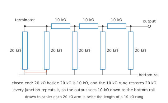
The family takes its name from the drawing, and the drawing is all the name refers to. Picture two horizontal rails. Along the top one, resistors are joined end to end in a chain, and at each junction of that chain another resistor drops to the bottom rail. Series element, shunt element, series element, shunt element, for as many repeats as the circuit needs. One series-plus-shunt pair is a section.
The shape only becomes useful once the two values are chosen deliberately. Give every series resistor the same value R, give every shunt arm twice that, 2R, and close the far end with one extra 2R arm down to the bottom rail. The network then has a property the drawing does not advertise, though it takes only a moment to check: each section leaves the next one facing what it faced itself.
Start at the closed end, where the extra arm and the first shunt arm both run down to the bottom rail. Side by side, two arms of 20 kΩ measure 10 kΩ. The series resistor of the next section adds straight onto that, bringing the total to 20 kΩ — one arm's worth again. Whatever the second section does, it does to the same 20 kΩ the first section was built against, and so do the third and the fourth.
Because the structure repeats, so does its effect. A voltage applied at one rung arrives at the output end halved compared with the same voltage applied at the neighbouring rung, one section closer. A chain built from two resistor values therefore produces contributions in powers of two, which is the arithmetic a binary number is written in. That is the job an R-2R ladder does inside a digital-to-analog converter: it turns a row of switches, each either on or off, into one voltage.
Practitioner
Reducing it from the closed end
Reduction normally begins where the supply is, and on a ladder that is the one place it cannot start. Three elements meet at the driven junction — the shunt arm there, the series resistor heading off into the network, and whatever is doing the driving — so the series and parallel tests both come back empty. At the closed end the situation is reversed. The terminating arm and the shunt arm beside it share both of their ends, which makes them a parallel pair and gives the reduction a place to begin.
From there the moves alternate. Combine that pair; add the series resistor that leads one step back towards the driven end; combine the running total with the shunt arm waiting at the next junction. Each round of three consumes one section, and the walk ends when it arrives at the junction you care about. Any ladder submits to that walk, whatever its values. In an R-2R ladder the running totals also stop changing.
Worked example — Walking a four-section ladder in from its closed end
The ladder has four shunt arms of 20 kΩ, three series resistors of 10 kΩ joining their junctions, and a terminating arm of 20 kΩ at the closed end. Every arm is switched to the bottom rail here, so the only question is what resistance the output junction presents.
At the closed end the terminator and the first arm are in parallel: 10 kΩ. The first series resistor carries that to the next junction as 20 kΩ. There the second arm sits across it and the total falls back to 10 kΩ, which the second series resistor restores to 20 kΩ. The third round produces 10 kΩ and then 20 kΩ, and at the output junction the last arm brings it to 10 kΩ.
The whole walk across four sections moved between two numbers. The output junction presents R however many sections stand behind it, and so does every junction along the way, counting its own shunt arm together with everything between it and the closed end.
Now take the terminating arm off and run the same walk. The closed end offers only the first shunt arm, 20 kΩ, and the series resistor makes that 30 kΩ. Against the second arm it comes to 12 kΩ where the intact ladder gave 10 kΩ, and the round after that differs again. The self-similarity fails at the very first step, and no step further along puts it back.
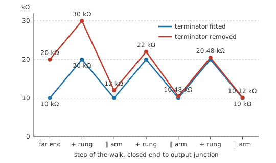
The terminator therefore does a job of its own: it lets the closed end behave like the ladder that would have carried on past it. Omit it, fit the wrong value, or return it to a rail other than the one the switches treat as zero, and every weight below the top one stops being a power of two.
Choosing R itself is a free hand within wide limits, and the choice gets made on grounds outside the ladder. Down in the low kilohms the network loads the reference harder and burns more current; up in the hundreds of kilohms the impedance at every junction rises, and board leakage, flux residue and the input current of whatever reads the output all start to register. The 10 kΩ used above sits in the ordinary middle of that range.
On a built board the network is easy to check before anything is powered. Hold every arm at the bottom rail, put a meter on ohms between the output junction and that rail, and the reading should be one R unit. Anything else means an arm, a rung or the terminator is not the part the drawing calls for.
Engineer
Each rung worth half the one before
The reduction settles what the ladder looks like from any junction. What appears at the output when the arms are thrown needs one more property: the network is linear, every element a resistance that holds its value. Linearity licenses superposition, so the output for any pattern of switches is the sum of the outputs the switches would produce one at a time. Set one arm to the reference, hold every other arm and the terminator at the bottom rail, find the output, and repeat.
Take the arm furthest from the output first. Its junction now carries two arms of 2R, one reaching the reference and one reaching the bottom rail, which is a divider of two equal resistances. Seen from that junction the pair is also a source, and Thévenin's theorem gives its internal resistance as the two arms in parallel — the 10 kΩ the reduction already produced.
Every step towards the output then does the same thing to that source. The series resistor adds on, taking the source resistance to 20 kΩ; the arm at the next junction, another 2R to the bottom rail, sits across it; two equal resistances divide the voltage in half, and the new source resistance is those two in parallel, back to R. Every rung repeats that same pair of moves, which is exactly what the collapse from the closed end guaranteed.
Worked example — Carrying the far-end bit out to the output
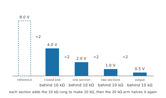
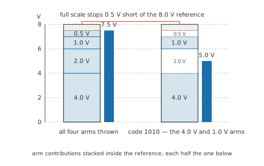
Reference 8.0 V, series resistors 10 kΩ, shunt arms 20 kΩ. Only the arm at the closed end is switched to the reference; the other three and the terminator are held at the bottom rail.
At the closed end the terminator and the switched arm divide the reference equally, putting that junction at 4.0 V behind a source resistance of 10 kΩ.
One section along, the source resistance is 20 kΩ and the arm at that junction is 20 kΩ, so the junction sits at 2.0 V. The next section repeats it for 1.0 V, and the third leaves 0.5 V at the output.
The reference has been halved four times over, which makes the arm at the closed end worth one sixteenth of it. Move a switched arm one rung nearer the output and one halving drops out of the chain, doubling its contribution. The arm at the output junction itself faces only the rest of the ladder, which the walk showed presents 20 kΩ there, so it divides once and is worth 4.0 V.
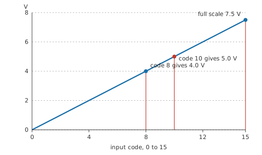
Throw every arm to the reference and the four contributions add to 7.5 V, one step short of the reference. With only the top arm and the third thrown — the code 1010 — the output is 5.0 V.
Running the same walk on any ladder
The two moves generalise to a ladder whose elements are all different, and only the bookkeeping grows:
- At the closed end, put the terminating element in parallel with the shunt element beside it. That combination is the source resistance at the first junction, and if either element reaches a driven rail, the junction voltage is that drive divided between the two.
- Add the series element that leads to the next junction onto the running source resistance.
- At that junction, take the voltage through the divider formed by the running source resistance and the shunt element there. The shunt element in parallel with the running source resistance is the new source resistance.
- Repeat steps 2 and 3 once per section until the output junction is reached.
R-2R is the special case where steps 2 and 3 return the same two numbers every time. The procedure collapses to one rule — a halving per section — and the walk needs no table of running values.
What the walk takes for granted
Every element has to be a fixed resistance. An element whose value moves with the voltage or current across it leaves the ladder with no single set of weights, and superposition does not apply at all.
The two destinations a switch can reach are treated as fixed potentials of negligible resistance. The reference must not sag when several arms are thrown to it at once, and the bottom rail must be the same zero for every arm. Anything in series with either destination lands inside the arm, indistinguishable from a resistor error.
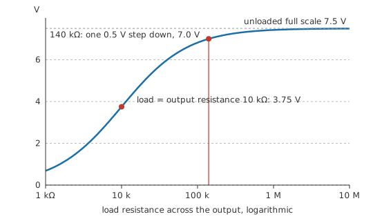
The output is assumed to be feeding nothing at all. Its resistance came out as 10 kΩ for every code, a genuine convenience, since the source impedance the next stage sees does not modulate with the code. Draw current from it, though, and that resistance drops voltage, which scales the whole transfer down, and does so non-linearly if the load varies with the output. A ladder is meant to feed a high-impedance input, in practice a buffer amplifier.
The terminator, finally, has to be present at 2R and returned to the switches' zero. Its absence is the one fault the walk cannot absorb, since it breaks the self-similarity every step rests on.
Professional
Matching, switches and monotonicity
Ratios carry the accuracy
No absolute resistance appears anywhere in the walk: every step divides one resistance by a sum of resistances, so scaling every element by a common factor leaves the output untouched. Build the same four sections from 1.0 kΩ and 2.0 kΩ and the closed-end junction still sits at 4.0 V. The current the reference has to supply into a switched arm does move, from 0.2 mA up to 2.0 mA.
The number to specify is therefore the match between the two values. How close either one sits to its nominal figure hardly enters into it. A monolithic R-2R network is thin film laser-trimmed on a single substrate: every element is deposited in one operation from one material, and each 2R arm is usually two R units in series, so a single unit geometry has to be right. The elements also share a die temperature, so the absolute drift of the film — which can be substantial — subtracts out of every ratio, and the published figure is a tracking coefficient rather than the temperature coefficient of a part on its own. A ladder built from separate resistors gets none of that, however close their tolerance. The parts come off different reels, sit at different points on the board's thermal gradient, and drift independently of one another.
The switch belongs to the arm
A switch in series with an arm adds its on-resistance to the arm, and the divider treats the sum as one resistance.
Take the arm as two R units of 10 kΩ plus a switch contributing 50 Ω. The arm becomes 20.05 kΩ, high by 0.25 %, and on the top bit that pulls the output from 4.0 V down to 3.995 V, an error of 4.99 mV. Set against the 0.5 V step of this four-bit ladder, an error that size is beneath notice. Run the same reference into a ladder of twelve bits, where one step is 1.953 mV, and the same switch has displaced the top bit by 2.56 LSB.
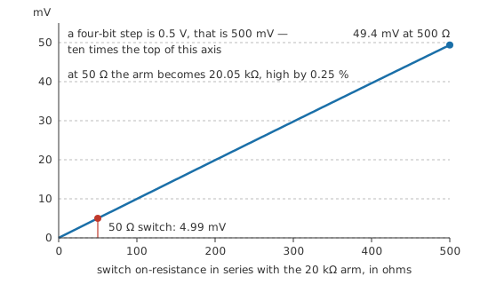
The error also depends on the code, since it appears only on arms thrown to the reference, so no single trim will remove it. Inside an integrated converter the answer is to scale the switches: the arms carry binary-weighted currents, so an on-resistance made inversely proportional to a bit's weight gives every arm the same drop across its switch, and a drop common to all arms behaves as a trimmable offset. Drops that differ arm to arm are the ones that bend the curve, and MOSFET switches on the die are sized bit by bit against that.
INL, DNL and the major carry
Integral non-linearity measures how far the output at a given code departs from a straight line through the converter's end points; differential non-linearity, how far one code-to-code step departs from the ideal step. Both are quoted in steps, the first reporting whether the curve bends and the second whether it climbs evenly.
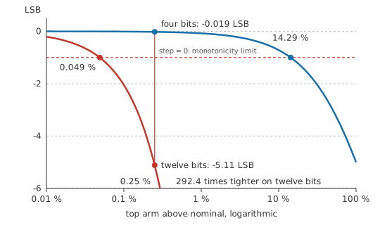
The hardest place on an R-2R ladder is the major carry, the transition from code 0111 to code 1000, where every switch changes state at once and the top arm alone takes over from the sum of all the others. Seen from the output junction the rest of the ladder is always a source behind 20 kΩ, open-circuit 7.0 V for the lower code, with the top arm hanging across it. A wrong top arm therefore moves both codes, the lower one along with the upper. With the switch error above, the lower code lands at 3.504 V and the upper one at 3.995 V, a step of 0.491 V against an ideal 0.5 V, a DNL of -0.019 LSB.
Push the top arm further out and the step shrinks to nothing, after which the output falls as the code rises. That is a monotonicity failure, and a converter inside a control loop that assumes a monotonic characteristic can hunt or latch on it. Reaching it here takes a top arm of 22.86 kΩ, some 14.29 % above nominal, which makes four bits a forgiving case. The headroom roughly halves with every bit added, so a twelve-bit ladder tolerates about 0.049 % on that arm, 292.4 times less. Monotonicity is bought with matching rather than supplied by the topology. Data sheets specify it as a parameter of its own, and where it matters more than die area a string of equal resistors tapped by switches is chosen instead, a structure whose output cannot go backwards. ADC and DAC basics sets out that comparison.
The same shape doing other work
"Ladder" is the name of a topology, and digital-to-analog conversion is only one use of it. A switched attenuator is a chain of series-and-shunt sections, each a fixed pad switched into or out of the signal path, with the port impedance designed to hold however many are engaged. Passive low-pass filters beyond first order are ladders too, series inductors and shunt capacitors in place of the resistors, and the reduction runs in from the far end on impedances instead. Published filter tables are lists of ladder element values for that reason.
Common mistakes
- Leaving the terminating arm off. The closed end then presents the wrong resistance, the repeat never starts, and every bit below the top one carries the wrong weight. The terminator is a working part of the network in its own right.
- "Precision resistors will make it accurate." Individually accurate parts from different reels still do not match one another, and matching is what the ladder consumes. A packaged network with an unremarkable absolute tolerance will beat a handful of close-tolerance discretes.
- Reducing from the driven end. Three elements meet at that junction, so no pair is available to start on. Work in from the closed end and every step has a pair waiting for it.
- The switch left out of the arm. On-resistance sits in series with the 2R and reads as a resistor error. It appears only on arms thrown to the reference, so it bends the transfer curve instead of shifting it.
- A load hung straight on the output. The ladder's source resistance is one R unit, and anything comparable across the output scales the whole transfer down; if the load varies with the output, it distorts it as well.
- Taking a single averaged DNL figure as the whole picture. One code's step out of specification is where a converter loses monotonicity, and the major carry is where that step is most at risk. Look at that transition specifically.
Frequently asked questions
Why 2R, and not some other multiple of R?
Only that ratio makes the network reproduce itself. Two arms of 2R in parallel come to R, and the series R restores 2R, so the section a given bit looks into is the same whichever rung it sits on. Other ratios analyse the same way and give a perfectly valid network, but the contributions are no longer powers of two and each bit needs its own coefficient.
How many different resistor values does an R-2R ladder need?
One, if each 2R arm is built as two R units in series. That is how monolithic networks are laid out: a single unit geometry repeated across the die, so only one value has to be trimmed and every element ages, heats and drifts alike. The same layout carries over to a ladder built from discrete parts.
Does the output resistance change with the code?
No, and that is one of the topology's quiet conveniences. Each arm reaches either the reference or the bottom rail, and both are meant to be sources of negligible resistance, so the network the output looks into is the same whichever way the switches are thrown. It works out at one R unit for every code.
Can I build an R-2R converter on a breadboard from ordinary resistors?
For a few bits, yes, and it is a useful thing to do once. With ordinary one-percent parts the mismatch between arms becomes comparable to a single step somewhere around the sixth or seventh bit, and bits added past that point are not resolving anything real. Use one value throughout, pairing units to make the arms, and measure the transfer curve rather than trusting it.
Are ladder networks only for digital-to-analog conversion?
No. The term describes an arrangement of alternating series and shunt elements, and the same shape turns up in switched attenuators, in passive filters built from inductors and capacitors, and in lumped models of transmission lines. What they share is the analysis: collapse the network from its far end inwards, one section per round.