
Quick Answer
An attenuator is a resistive network that reduces a signal by a specified amount, normally stated in decibels, while presenting a defined impedance at its input and at its output. A voltage divider attenuates but specifies neither impedance; pad topologies with a third element fix both.
Intuition
Reducing a signal by a stated amount
A signal often arrives larger than whatever has to receive it. A source swings volts into an input that tolerates a few hundred millivolts; a transmitter's output goes to a measuring instrument built for milliwatts. Something has to bring the level down by a known amount and leave the rest of the signal alone.
A pair of resistors will do it. A chain of 9.0 kΩ and 1.0 kΩ across 10.0 V puts 1.0 V at the junction between them, a tenth of what went in. That circuit is a voltage divider. Calling the same pair an attenuator is a statement about the specification written against it rather than about the resistors themselves. A divider is picked to produce an output voltage; an attenuator is bought or built to produce a ratio, held to a tolerance, over a stated range of frequencies.
The ratio is usually quoted in decibels. A tenth of the voltage is 20.0 dB; half the voltage is 6.02 dB, close enough to six that these are called 6 dB pads; a hundredth is 40.0 dB, the 20 dB figure plus itself. Ratios multiply where decibel figures add, and a signal path is usually a chain of stages, so decibels turn a run of multiplications into a running total.
The specification carries a second number as well. Signal paths are built around a resistance — 50 Ω in most instrument and radio work, 75 Ω in video and aerial systems — and the equipment at each end expects to meet that value in whatever is inserted between them. A divider of two resistors cannot supply it at both ends, and the three-element pads further down this page are what answer that shortfall.
Practitioner
Working in decibels
Attenuation is quoted as a positive number of decibels: a 20 dB pad divides the voltage by ten. The same part is sometimes described as a gain of −20 dB — the sign the logarithm actually produces — and the two descriptions mean the same thing.
The factor of 20 traces back to how the unit is defined. The decibel is defined on a power ratio and carries a factor of 10. Power into a fixed resistance goes as the square of the voltage across it, and a square inside a logarithm comes out as a factor of two, so the voltage form uses 20 where the power form uses 10. Both give the same figure when the input and output impedances are equal — the ordinary case for a pad, and the reason one number can serve for both.
The ratio itself comes from the divider expression, with the output arm on top:
Worked example — A divider ratio put into decibels
A source of 5.0 V feeds 3.0 kΩ in series with 1.0 kΩ to the reference rail. The output is the voltage across the lower arm, with nothing connected to it.
The tap sits at 1.25 V, so input over output is 4.0. Through the decibel expression that ratio becomes 12.04 dB.
The same result reads as two stages. A ratio of 4 is two 2:1 steps in cascade, and 6.02 dB counted twice arrives at the same figure. In power the reduction looks steeper: into one impedance the load receives one part in 16.0 of what a direct connection would have given it.
Connect a load to the output and every figure above moves, since neither resistance was chosen with any impedance in mind. What the arithmetic describes is a divider that happens to attenuate, one specification short of an attenuator.
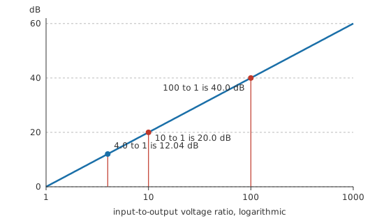
On a bench, 3 dB is half the power, 6 dB is half the voltage, 20 dB is a tenth and 40 dB a hundredth; those four figures cover most of what comes up, and anything else is a short calculation. Stage figures add, so a 10 dB pad ahead of a 6 dB pad gives 16 dB, provided each is terminated as it was designed to be.
Fixed pads turn up as screw-on coaxial parts on a bench, as small networks on a board ahead of a converter or a mixer, and as switched sections inside instruments. A scope probe is one too. In each case the pad is chosen for a figure in decibels and an impedance, and both belong to the part before it belongs to any particular circuit.
Engineer
Why a pad needs a third element
A pad in a 50 Ω system has three things to satisfy at once: the voltage ratio, the impedance looking in with the output terminated, and the impedance looking back with the input driven from the system. A network of two resistors offers two values to choose, and two free numbers will not stretch across three requirements. Something has to give, and in a two-element pad what gives is a port match.
The two-element pad is still the standard answer wherever only one end has to be right, and it falls out in a few lines. Take a series arm feeding a shunt arm, with the load Z₀ across the shunt arm. The shunt arm and the load together form one resistance:
Call that combination P. The whole output voltage appears across it, so the network is a divider of the series arm against P, and the voltage ratio N is Z₀ ⁄ P once the input impedance is forced to Z₀. Rearranged, P = Z₀ ⁄ N, and the series arm is whatever is left over, Z₀ − P = Z₀ (N − 1) ⁄ N. The two expressions between them fix both arms.
Worked example — One 6 dB reduction, three ways
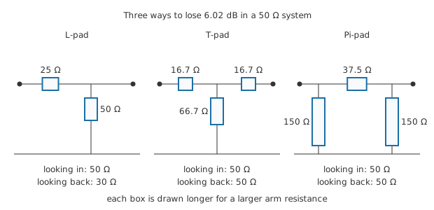
Every pad here is designed for 6.02 dB in a 50 Ω system, which is a voltage ratio of 2.
The L-pad follows straight from the two equations above: a series arm of 25 Ω and a shunt arm of 50 Ω. Terminated, the shunt arm and the load come to 25 Ω, and adding the series arm returns 50 Ω at the input. Now look back into the output with the input driven from the system impedance. The shunt arm sits in parallel with the series arm plus that source, giving 30 Ω. The input sits at the design value and the output does not, which is exactly the match a two-element pad has to give up.
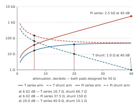
The symmetric T-pad has two equal series arms with one shunt arm between them, which is three elements but only two distinct values, and only two conditions to meet, since the symmetry makes the two ports identical. The design expressions are R_ser = Z₀ (N − 1) ⁄ (N + 1) and R_sh = 2 Z₀ N ⁄ (N² − 1), giving arms of 16.7 Ω and 66.7 Ω. Check it: terminated, the shunt arm parallels the far series arm plus the load to give 33.3 Ω, and the near series arm brings the input to 50 Ω. The same sum runs identically from the other end.
The Pi-pad is the same trick turned inside out — one series arm between two shunt arms — with R_ser = Z₀ (N² − 1) ⁄ (2 N) and R_sh = Z₀ (N + 1) ⁄ (N − 1), here 37.5 Ω and 150 Ω. It attenuates by the same figure and matches at both ports as well. Which topology gets built is decided on the arm values themselves: deep pads push a T-pad's shunt arm towards very small resistances and a Pi-pad's series arm towards large ones, and the more comfortable set of numbers wins.
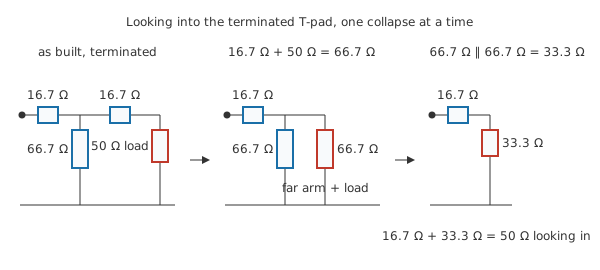
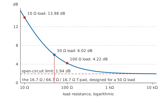
A pad's figure belongs to the pad and its termination together. Feed the T-pad above with 5.0 V and leave its output open: no current flows in the far series arm, the near arm and the shunt arm are a plain divider, and the output rises to 4.0 V where a 50 Ω load would have held it at 2.5 V. That is 1.94 dB of attenuation instead of 6.02 dB. A high-impedance meter across an unterminated pad reads a figure that belongs to the measurement rather than to the pad.
Unequal impedances at the two ends put the L-pad back in play, this time as the only resistive option. Matching a 75 Ω source to a 50 Ω load takes a series arm on the high side and a shunt arm on the low side, and the two matching conditions — one at each port — use up both values between them, leaving nothing free for the ratio: 43.3 Ω and 86.6 Ω. The attenuation is then whatever those values produce, 5.72 dB, and no resistive network matching those two impedances can lose less. That figure is a power ratio between two different impedances, so it is not the pad's voltage ratio expressed in decibels; the two coincide only when the ports are equal.
Every pad above is built from linear resistances, so it attenuates a millivolt and a hundred volts by the same factor and does not care which port is the input. A pad's termination has to be real as well: it works into the impedance it was designed for, and impedance matching is a separate job it happens to be compatible with. The loss is genuine too. A resistive pad throws away the power it removes, so where the loss cannot be afforded a transformer changes impedance without that penalty, at the cost of working only over a band and not at DC.
Professional
What a real pad has to survive
Where the heat lands
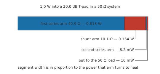
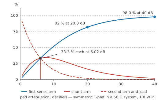
Attenuation is dissipation, and a pad does not share it out evenly. Send 1.0 W into a 20 dB T-pad built for the same 50 Ω system, whose arms work out at 40.9 Ω and 10.1 Ω. The input terminals sit at 7.07 V drawing 141 mA, and every milliamp of that passes through the first series arm:
That arm takes 0.818 W, some 82 % of everything entering the pad. The shunt arm takes 0.164 W, the second series arm 8.2 mW, and 10 mW leaves through the output. The deeper the pad, the more lopsided this gets: at 30 dB or 40 dB the first arm is carrying essentially the whole input power on its own. Sizing all three arms from a fifth of the total, as an even split would suggest, destroys the first one and leaves the others cold. Power ratings belong to individual arms, and the power dissipation a pad turns to heat has to leave through its body and connectors.
Bandwidth
A pad's arms in a 50 Ω system are tens of ohms, so the stray capacitance across a resistor forms a far shorter time constant than the same capacitance across a divider built from megohms, and low-impedance pads stay flat to high frequencies for that reason alone. Construction sets the practical limit instead: lead and via inductance in series with each arm, capacitance between arms and to the enclosure, and the quality of the ground return. Thin-film chip parts on a controlled-impedance line hold their figure into the gigahertz; the same values built with leads and through-holes drift far lower. A frequency range and a flatness figure across it are as much part of the specification as the attenuation.
A matched pad also improves what a source sees when the load is poorly matched, and it does so twice over: a reflection travels through the pad on the way out and again on the way back, so 6.02 dB of pad buys 12.04 dB of improvement in the reflected signal. Fitting a small pad in front of an awkward load is a standard fix, paid for in signal level.
Step and programmable attenuators
A step attenuator is several pads in one box, each switched in or out, in binary-weighted values so that a handful of sections cover a wide range in small steps. Mechanical versions use relays or rotary switches; programmable ones use FET switches and arrive as digitally controlled ICs. The switch is then part of the signal path: its on-resistance sits in series with an arm and upsets small steps, while its off-capacitance leaks signal around a section that is supposed to be out of circuit and limits how much isolation the largest steps really deliver. A potentiometer is a continuously variable divider whose impedances move as the wiper does, which keeps it outside this family.
The 10:1 probe
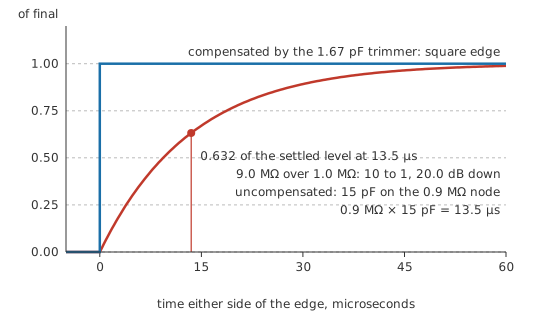
A scope probe marked ×10 is a 20.0 dB attenuator built into a lead: 9.0 MΩ in the probe body against the instrument's own 1.0 MΩ. Resistively that is a clean tenth. The scope's input capacitance and the cable's, together perhaps 15 pF, sit across the lower arm and ruin it. With the two arms in parallel giving 0.9 MΩ, the node has a time constant of
which comes to 13.5 µs. Anything faster than that arrives rounded off. The fix is to divide capacitively in the same proportion as resistively, which means a trimmer of about 1.67 pF across the upper arm. Adjusted correctly, the capacitive divider and the resistive divider agree at every frequency and the attenuation is flat. The square-wave calibrator output on the front of a scope exists for that adjustment; a mis-set trimmer shows as overshoot or as sagging corners on the displayed edge.
Safety
Attenuation is not protection. A ×10 probe divides the signal, and dividing does not raise what the probe body and its lead can safely stand: the probe carries its own working-voltage and CAT rating, and that rating, not the division ratio, is the limit. The same applies to a pad in a power path — it is rated for a maximum input power, above which an arm fails, often by going open and putting the full input on the output. Work to the practices in electrical safety fundamentals whenever a signal path carries hazardous voltages.
Common mistakes
- A pad measured with nothing on its output. The nominal figure assumes the design termination at both ends, and an open output leaves a T-pad or Pi-pad under-attenuating by several decibels. Fit the load, or a through-terminator, before believing a reading.
- "A 6 dB pad halves the power." It halves the voltage, which quarters the power. Half the power is 3 dB, and mixing the two conventions is the commonest decibel slip there is.
- Every arm given the same power rating. In a deep pad the input series arm takes almost all of the dissipation and the output arms take almost none. Rate the first arm for the pad's full input.
- Two pads cascaded and their figures added, without terminating either. The second pad's input impedance is only the design value when its output is loaded, so an unterminated chain delivers neither its stage figures nor their sum.
- A ×10 probe treated as a purely resistive divider. Its DC ratio is right whatever the trimmer is doing; its response to an edge is not. Compensate against the calibrator every time the probe moves to a different channel or instrument.
- An attenuator reached for as input protection. A pad scales a steady signal by a fixed factor and goes on scaling a fault by the same factor, so a hundred volts arriving at a 20 dB pad still delivers ten volts to whatever follows.
Frequently asked questions
Is an attenuator just a voltage divider?
Electrically a two-element pad is exactly that. The difference is in what is specified. A divider is designed around a wanted output voltage and its impedances fall where they fall; an attenuator is specified as a ratio held to a tolerance, over a frequency range, with a defined impedance at each port. Meeting the impedance requirement at both ends is what forces a third resistor into the circuit.
Why is it 20 log for voltage and 10 log for power?
The decibel is defined on power. Voltage reaches power through a square, and squaring inside a logarithm doubles it, so the voltage form carries 20 where the power form carries 10. The two agree numerically when the input and output impedances are equal, which is why a matched pad can be quoted as one figure without ambiguity.
Which should I use, a T-pad or a Pi-pad?
For equal port impedances both give identical performance, so pick on the arm values. A deep T-pad needs a very small shunt arm, where lead resistance and tolerance start to matter; a deep Pi-pad needs a large series arm, whose stray capacitance matters instead. Shallow pads usually build more comfortably as a Pi, deep ones as a T, and available resistor values often settle it.
Can I make a matched attenuator with just two resistors?
You can, provided one port is allowed to go unmatched. Two resistors give two free values, while the specification asks for three things: the ratio and both impedances. An L-pad spends its two values on the ratio and one impedance. The exception is matching two unequal impedances, where the two matching conditions use up both values and the attenuation is whatever falls out, with a minimum below which no resistive network can go.
Do attenuators work at DC?
Resistive ones do, down to zero frequency, and they attenuate in both directions since nothing in a resistor network distinguishes input from output. That is one of their advantages over transformers and over reactive matching networks, which need an AC signal and a limited band. What a resistive pad cannot do is change impedance without loss.