
Quick Answer
A strain gauge is a resistor bonded to a surface so that stretching the surface stretches the gauge. Pulling it longer and thinner raises its resistance by a fraction of a per cent, and a Wheatstone bridge turns that fraction into a few millivolts that an amplifier can work with.
Intuition
A resistor you glue to something
Draw a line in ink across a rubber band and pull the band. The line grows longer and thinner as the rubber under it does. A strain gauge is that line made of metal foil: a fine conducting track bonded to a surface, so that when the surface stretches the track stretches too, growing longer and narrower and therefore harder to push current through.
The difficulty is the size of the effect. Strain is a ratio, a change in length divided by the original length, so it has no unit of its own and it is quoted in microstrain — parts per million. Metals in a working structure spend their lives at a few hundred microstrain, and the interesting question is usually whether a part is at two hundred or at eight hundred, not whether it has broken.
A 350.0 Ω gauge carrying 500 microstrain, a stretch of five parts in ten thousand, changes by 0.359 Ω. That is 0.1025 % of what it started with, and the wanted signal sits underneath a resting resistance 976 times larger that does not move at all.
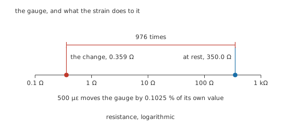
The change and the part it hides in, on one logarithmic axis.
The resistor itself is ordinary. Everything difficult about strain gauges comes from that ratio, because a part's tolerance, its drift with temperature and the resistance of the wires reaching it are all the same size as the answer or bigger.
Practitioner
Gauge factor, and the bridge that subtracts the rest
How much resistance a gauge gives per unit of strain is a property of the gauge, and it has a name: the gauge factor, the fractional change in resistance divided by the strain that produced it. It is a plain ratio, so it carries no units.
Metal-foil gauges cluster close to 2, and the 2.05 used throughout this lesson is an illustrative figure rather than a catalogue one; a real gauge arrives with its own measured value and a tolerance on that value, and both belong in your error budget. Semiconductor gauges reach much larger factors and give back most of the advantage in temperature sensitivity and in a characteristic that is no longer straight.
That leaves the measurement problem. Handing 350.4 Ω to an ohmmeter and asking it to tell you the last three digits is a losing proposition, and it gets worse as the wires get longer. A Wheatstone bridge sidesteps the whole question by subtracting instead of measuring: two voltage dividers across one supply, with the detector reading only the difference between their taps. Give the gauge three fixed companions of the same nominal value and the resting 350.0 Ω appears identically in both legs, cancels, and leaves the change behind.
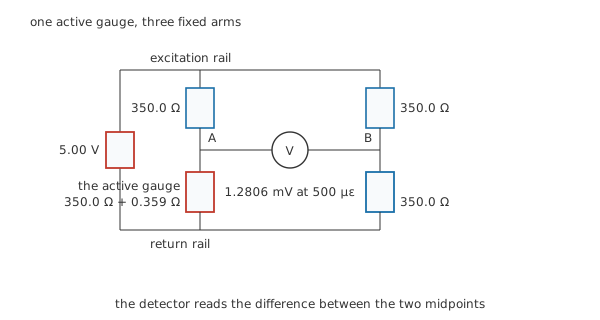
One active arm makes a quarter bridge. The detector sees the two midpoints and nothing else.
Worked example — A quarter bridge on one gauge
The gauge is 350.0 Ω with a gauge factor of 2.05, and the surface it is bonded to carries 500 microstrain. The bridge runs on 5.00 V.
Gauge factor and strain together give a resistance change of 0.359 Ω, so the active arm becomes 350.4 Ω while the other three sit at 350.0 Ω. In fractional terms the arm has moved by 0.1025 %.
Its leg's tap now sits above the other leg's, and the difference between them is 1.2806 mV. Through an amplifier of 500 V/V that becomes 0.6403 V, which is a signal a converter can take seriously.
The bridge lesson works through balance, deflection and the arithmetic of the arms; this one takes that result and asks what the gauge does with it.
Engineer
One active arm, or two, or four
A quarter bridge has one gauge and three fixed resistors. A half bridge puts a second gauge in the arm above or below the first, positioned so that the two strains oppose — the classic case is a beam in bending, with one gauge on the face that stretches and one on the face that compresses. A full bridge makes all four arms active, with opposite arms moving together and adjacent arms moving against each other.
The output follows directly. At 500 microstrain on 5.00 V, the quarter bridge gives 1.2806 mV, the half bridge 2.5625 mV and the full bridge 5.1250 mV. Doubling and quadrupling the sensitivity is the obvious gain; the quieter one is that a half or full bridge only responds to strains that differ between its arms, which is how a load cell ignores the temperature and the bending it was not built to weigh.
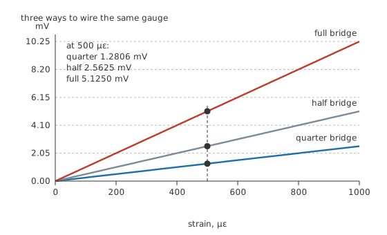
Three configurations, one shared millivolt scale, all of them straight to the eye.
The quarter bridge is not quite a straight line
A quarter bridge changes one arm of one divider, which changes that divider's total resistance as well as its ratio, so its output bends very slightly away from proportionality. The shortcut most people use — excitation times gauge factor times strain, divided by four — runs high by 0.05125 % at the strain worked above. At a hundred times that strain the same shortcut would be off by several per cent, which is why load cells that have to stay linear across their whole range use half and full bridges: the opposing arms hold each leg's total resistance constant, and the bend disappears rather than being corrected for.
A warm specimen writes its own strain
The alloy a gauge is made from has a temperature coefficient of its own, and the bridge has no way to ask whether a change in the active arm came from stretching or from warming.
Take an illustrative 12 ppm/°C and warm the gauge by 20 °C. The arm goes to 350.1 Ω, a change of 0.084 Ω, and dividing that fractional change by the gauge factor turns it into 117 microstrain of pure fiction. The strain being measured is only 4.27 times larger, so a laboratory that drifts by a few degrees over an afternoon has already spent a quarter of the reading. In bridge output that drift is 300.0 µV sitting under the 1.2806 mV you wanted.
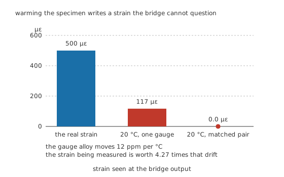
Two of these bars are the same measurement. Only one of them is real.
The cure is to give the drift a partner. Two gauges in the same leg, held at the same temperature, drift by the same fraction, and an equal fractional change in both arms of a leg leaves that leg's ratio untouched: the apparent strain falls to 0.0 microstrain. What survives is a change of scale rather than an offset, because the leg's total resistance has moved — the sensitivity shifts by 0.0240 %, which is small enough to ignore in most work and calculable when it is not. Half and full bridges get this protection as a side effect of their layout, and a quarter bridge earns it by adding a dummy gauge, bonded to an unloaded piece of the same material and kept in the same air. Temperature effects on resistance covers the underlying behaviour.
The alloy's own coefficient is not the whole temperature story. A gauge bonded to a specimen also follows that specimen as it expands, and gauges are sold matched to the expansion of a particular material for exactly that reason. The arithmetic above covers only the first effect.
Professional
What limits the reading
Excitation buys signal and heat together
Bridge output is proportional to excitation, so more volts means more millivolts, and the temptation is obvious. Dissipation is the other half of the trade.
At 2.00 V the quarter bridge gives 0.5122 mV and the four arms turn 11.43 mW into heat. At 5.00 V it is 1.2806 mV and 71.41 mW. At 10.00 V, 2.5612 mV and 285.6 mW. Five times the excitation buys five times the signal and twenty-five times the heat.
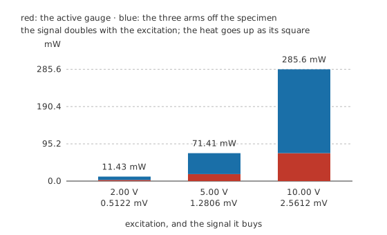
The gauge's own share is the lower segment, and it is the share that matters.
Three of those arms sit on a circuit board where heat is somebody else's problem. The fourth is glued to the thing being measured, and its 2.857 mW, 17.86 mW or 71.43 mW has to leave through the bond and into the specimen. A gauge on thick aluminium sheds that easily; the same gauge on thin plastic warms the material under it, which expands, which the gauge dutifully reports as strain. Manufacturers state a maximum excitation or a maximum power density for exactly this reason, and it depends on what the gauge is stuck to. Pulsed excitation — energise, sample, switch off — raises the signal without raising the average heat, at the cost of settling time on every reading.
The noise floor is not the problem
Seen from its two midpoints, a bridge of four equal arms is a source of 350.0 Ω: each leg contributes its pair in parallel, and the two legs add. Any resistance generates thermal noise, and the amount depends on the resistance, the absolute temperature and how much bandwidth the measurement is willing to accept.
At 293 K and a noise bandwidth of 10.0 Hz, that source contributes 7.526 nV. Narrow the measurement to 1.0 Hz and it falls to 2.380 nV; open it to 100 Hz and it rises to 23.80 nV, because noise grows with the square root of bandwidth rather than with bandwidth itself. Expressed as strain, those three are 0.000929, 0.002938 and 0.009292 microstrain.
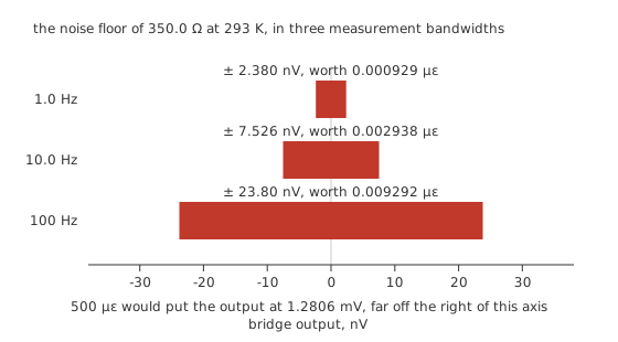
Bands at true scale. The strain signal is five decades to the right and cannot share the axis.
Against 500 microstrain those figures are nothing, and amplification does not change the comparison: 500 V/V of gain takes the signal to 0.6403 V and the noise to 3.763 µV, both multiplied by the same number.
So the bridge's own thermal noise is never what stops you. What stops you is everything in the earlier sections plus the amplifier's input offset and its drift, which arrive at the same place as the signal and are not distinguishable from it. That is the job an instrumentation amplifier exists for: a few millivolts of difference riding on a common-mode voltage of about half the excitation, with the offset and drift specified rather than hoped for.
Everything between the gauge and the amplifier
Lead resistance lands inside the arm it belongs to. Two wires out to a remote gauge put both of them in series with it, which adds a fixed offset the bridge reads as strain and a drift as the cable's own temperature changes. Three wires split the pair between two arms so that the balance condition subtracts one from the other, and the same four-terminal thinking that shunt resistors use applies whenever the resistance being measured is small compared with the wiring.
The bond is part of the instrument. A gauge reports the strain of the adhesive layer it sits in, so a bond that creeps under sustained load reports a strain that decays, and one that is partly unstuck reports a strain that is partly imaginary. Surface preparation and cure schedule are not optional steps.
Alignment matters more than it looks. A gauge grid responds mostly along its own axis and a little across it, so a grid fitted a few degrees off the strain direction reads low, and it also picks up part of the perpendicular strain. Manufacturers quote a transverse sensitivity for the grid pattern.
The whole chain also wants checking against something known rather than trusted. Switching a precision resistor across one arm produces a resistance change you can compute, and therefore an apparent strain you can compute, so the reading it produces tests the bridge, the amplifier and the converter together. The residual questions are the same ones tolerance and precision and accuracy against resolution raise everywhere else.
Common mistakes
- Reading a quarter bridge and calling the answer strain. Without a dummy gauge or a compensated layout, part of what you read is the temperature of the room. Establish what the bridge does when the specimen is unloaded and warming.
- Fitting the compensating gauge in the opposite arm rather than the adjacent one. Opposite arms add their changes at the output and adjacent arms subtract, so a diagonal dummy doubles the drift it was meant to remove.
- Raising the excitation to get a bigger reading. The signal grows with it and the heat grows with its square, and the quarter of that heat inside the active gauge lands in the specimen you are measuring.
- Trusting the four-times shortcut on a quarter bridge at large strain. It is fine at a few hundred microstrain and wrong by per cent at a few thousand, always in the generous direction.
- Ignoring the lead wires on a remote gauge. Their resistance is inside the arm, their drift is inside the arm, and at these signal levels a few tenths of an ohm is not a rounding error.
Frequently asked questions
What does gauge factor actually mean?
It is the fractional change in the gauge's resistance divided by the strain that caused it, so a factor of 2 means a strain of one part per million moves the resistance by two parts per million. It is a pure ratio with no units, and it is the number that converts an electrical reading back into a mechanical one.
Why 350 ohms, and why do 120 ohm gauges exist too?
Both are long-established standard values, and the choice is a trade between signal and heat. For a given excitation a lower resistance draws more current and dissipates more, which is harder on a delicate specimen; a higher resistance dissipates less and is more sensitive to the resistance of the leads and connectors around it.
Can I read a strain gauge with an ordinary multimeter?
You can see that it is intact and roughly the right value, which is a worthwhile check before wiring anything. You cannot measure strain that way. The change is around a tenth of a per cent of the reading, below the resolution of most handheld meters and far below their accuracy, and it moves with the temperature of your leads while you watch.
Does the gauge need to be on the surface that is stretching?
It needs to be bonded to a surface that stretches by the amount you care about. On a beam in bending the two faces move opposite ways and the neutral axis in between moves not at all, so where the gauge goes decides what it reports, and a half bridge uses that deliberately by putting one gauge on each face.
What is the difference between a strain gauge and a load cell?
A load cell is a piece of metal designed to deform in a known, repeatable way, with gauges bonded to it in a full bridge and the whole assembly calibrated in force units. The gauges are the sensing element; the metal, the arrangement and the calibration are what turn them into an instrument you can trust to weigh something.