
Quick Answer
Tie a 555's threshold and discharge pins to a single capacitor charged through one resistor, and a brief dip on the trigger starts a pulse that ends when the capacitor reaches the upper tap. The length is the logarithm of three multiplied by the resistor and the capacitor, and nothing else.
Intuition
Let go of the button
You let go of the stairwell button almost at once, and the light stays on anyway. It stays on for about the same time every night, whether you press it for an instant or lean on it, and it goes off by itself. Nothing about the length of the press survives into the length of the light.
That separation is the whole idea. There is an event, which is short and whose length carries no information, and there is an interval, which is long and whose length was decided in advance by whoever installed the thing. The event starts the interval. It does not measure it, shape it or end it.
Almost everything that has to wait works this way. A camera shutter, a windscreen wiper's delay, the pause before a hall door relocks, the pulse a sensor sends to say something went past. Each of them turns a moment into a duration.
The 555 monostable is the same arrangement built out of one resistor, one capacitor and one comparison. It is the running version of the timer with the loop cut open: instead of restarting itself forever, it runs once and waits.
Practitioner
From empty up to the tap
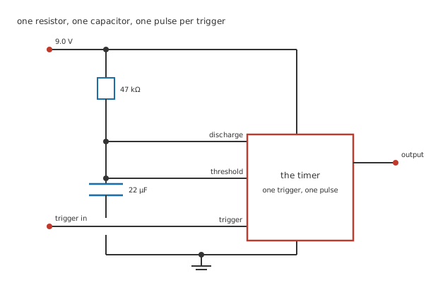
Four junction dots. The capacitor's ground leg crosses the trigger run without joining it, so that crossing is drawn with a break.
The architecture is the one the timer lesson set out: a divider making two taps, two comparators watching them, a latch between the comparators and the output, and a transistor on the discharge pin that can short the capacitor to ground.
Wire it like this and there is only one resistor in the timing path. 47 kΩ runs from the 9.0 V supply down to 22 µF, and both the discharge pin and the threshold pin sit on the top of that capacitor. While the circuit is idle the discharge transistor is on, so the capacitor is held at nothing at all.
A dip on the trigger below 3.0 V flips the latch. The discharge transistor lets go, the capacitor starts filling through the resistor, and the output goes high. It stays high until the capacitor arrives at the upper tap, at which point the threshold comparator flips the latch back, the transistor shorts the capacitor out again, and everything is where it started.
Worked example — How long the pulse lasts
The capacitor starts at nothing and has to reach 6.0 V, which is two thirds of the way to the supply.
An exponential covering two thirds of its gap leaves a third of it, and a third takes the logarithm of three multiplied by the time constant. Here the time constant is 1.034 s.
So the pulse is 1.136 s, and the supply has cancelled out of it: the tap is a fraction of the supply, so a sagging battery moves the target and the curve together.
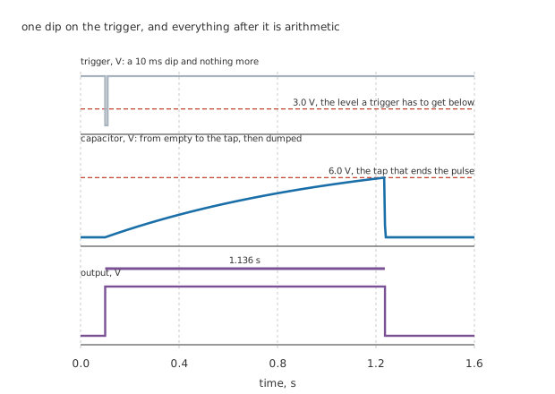
The trigger is over long before the pulse is. That is the arrangement working properly, not a drawing convenience.
Notice what the middle panel is not. It is not the swing between two taps that the astable draws, and it is not a full RC charging curve either. It starts at zero, it stops at one tap, and then it is thrown away. One crossing, once.
Worked example — And the constant everybody writes instead
Datasheets and half the internet give the pulse width as one point one multiplied by the resistor and the capacitor, which here would be 1.137 s.
That is not a different formula. One point one is a rounding of the logarithm of three, and the rounding is high by 0.126 %.
Nobody minds, and the figures in the next layer show why: an ordinary 20 % capacitor moves the answer 158 times further than the rounding does.
Every value in this lesson is invented and belongs to no real part. They avoid the RC lesson's pair deliberately, so nothing here repeats a scenario you have already worked through.
Engineer
Everything hangs on the capacitor
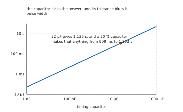
A decade of capacitance is a decade of time. The thick bar is what one part's tolerance does to the answer.
Both timing components enter the formula the same way, so either will move the pulse and neither changes its shape. In practice the capacitor is the coarse dial and the resistor is the fine one, because capacitors come in far fewer values and the resistor is the easier part to trim.
The awkward part is that the capacitor is also the part you know least well. A film capacitor might hold a few per cent; an electrolytic of the size you need for a pulse of a second is often specified at twenty per cent and sometimes at minus twenty to plus eighty.
Worked example — What one part's tolerance costs
The width is directly proportional to the capacitance, so a 20 % part maps straight onto a 20 % pulse.
That is 909 ms at one end and 1.363 s at the other.
A span of 454 ms, around a nominal 1.136 s. If the application needs better than that, the capacitor is what has to improve, and no amount of care with the resistor helps.
There is a second trap in this circuit that has nothing to do with tolerance, and it catches people who are testing with a push-button.
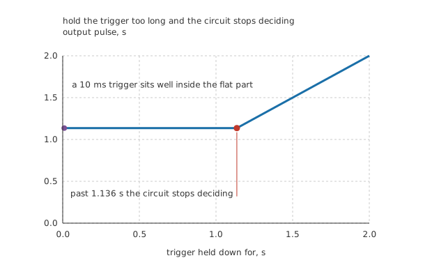
Left of the marker the circuit is choosing the length. Right of it the trigger is, and the timing components have stopped mattering.
The trigger input is a level, not an edge. While it is held below the lower tap the lower comparator keeps the latch set, and the threshold comparator cannot clear it. So the output stays high for as long as the trigger is held, and the pulse you measure is the press, not the circuit.
A 10 ms trigger, or anything else comfortably shorter than 1.136 s, is fine. A finger on a button is not: a short press is a tenth of a second and a deliberate one is half a second, both of which are inside the flat part here, but shorten the pulse to a few milliseconds and every press becomes its own answer. The usual fix is a small capacitor and a pull-up on the trigger pin, so that a level becomes an edge before the chip ever sees it.
Professional
After the pulse, before the next one
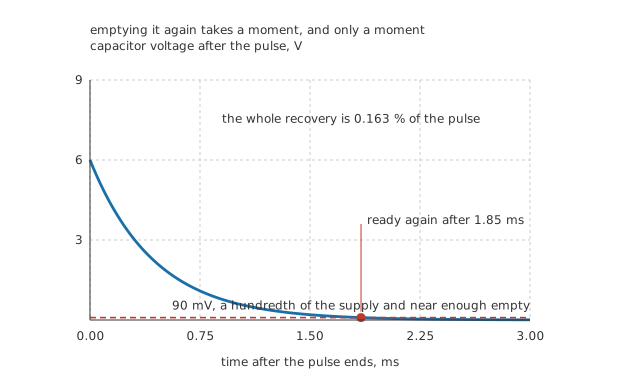
The horizontal axis is milliseconds. The pulse this follows was more than a second long.
Emptying the capacitor is not instant, and the circuit is not ready for another trigger until it is done. The discharge transistor is a switch with resistance, and that resistance and the same capacitor make their own time constant.
Worked example — Getting ready again
Call the discharge transistor 20 Ω when it is on. With the same capacitor, that is a time constant of 440 µs.
The capacitor falls from the upper tap towards zero, and it is near enough empty by 90 mV, a hundredth of the supply. Reaching that takes 1.85 ms.
Which is 0.163 % of the pulse it follows. For a pulse of a second this is invisible; for a pulse of ten microseconds it would be most of the story.
The largest useful resistor
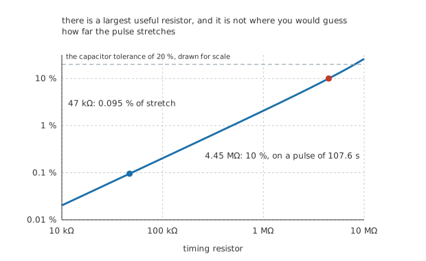
The dashed rule is the capacitor's own tolerance, drawn for scale. The two do not meet until eight megohms.
Wanting a longer pulse, the obvious move is a bigger resistor, and the obvious move runs into something. The threshold pin is an input, and inputs draw current. That current comes out of the same charging current the resistor supplies, and as the resistor grows the charging current shrinks while the pin's appetite does not.
Worked example — Where it stops working
At the moment of crossing, the resistor is delivering the remaining gap over its own value: 63.8 µA.
Against that, a threshold pin drawing 100 nA is 0.157 % of the current, and it stretches the pulse by 0.095 %. Nothing to worry about.
Raise the resistor and the picture changes, because the capacitor is no longer aiming at the supply. It is aiming lower by the pin's current multiplied by the resistor, and at 4.45 MΩ that target has dropped to 8.555 V. The pulse comes out 10 % long, at 107.6 s instead of the arithmetic answer.
So the ceiling is real but it is generous, and it is not where most people put it. Megohms are fine. Tens of megohms are not, and by then the capacitor's own leakage is competing with the charging current too, which the formula does not model at all.
Building one
Pick the capacitor first, because it is the part with the worst tolerance and the fewest available values. Then trim the resistor to land on the pulse you want.
Make the trigger an edge. A capacitor and a pull-up on the trigger pin cost almost nothing and remove the entire class of problem in the previous layer.
Leave room for recovery if the pulses come close together. A hundredth of the pulse is nothing at a second and everything at ten microseconds.
Decouple the supply. The output switches under load twice per event, and a rail that dips takes both taps down with it at exactly the wrong moment.
Do not chase the last per cent. The formula is exact and the parts are not, and a circuit that needs better timing than twenty per cent wants a counter and a crystal rather than a better electrolytic.
Common mistakes
- Holding the trigger down past the end of the pulse — the trigger input is a level, not an edge, so the output follows the button and the timing components decide nothing. Anything shorter than 1.136 s is fine; a finger is not, once the pulse gets short.
- Trusting the nominal width — 22 µF at 20 % gives anything from 909 ms to 1.363 s, a span of 454 ms. The formula is exact; the capacitor is not.
- Thinking 1.1 RC is a different formula — it is the logarithm of three rounded, high by 0.126 %, which is 158 times smaller than what the capacitor's tolerance is already doing.
- Reaching for megohms to get a long pulse — the threshold pin's own 100 nA is 0.157 % of the charging current at 47 kΩ but a real competitor at 4.45 MΩ, where the pulse runs 10 % long. Increase the capacitor instead.
- Retriggering before the capacitor is empty — the discharge transistor's 20 Ω and the capacitor need 1.85 ms to clear it, and a trigger arriving inside that window gives a short pulse rather than a full one.
- Regulating the supply to stabilise the pulse — it does nothing, because 6.0 V is two thirds of whatever the supply happens to be. What moves the pulse is the resistor and the capacitor.
Frequently asked questions
Where does the logarithm of three come from?
The capacitor starts empty and has to reach two thirds of the supply, so it must cover two thirds of the gap it started with and has one third left when it arrives. An exponential takes the logarithm of that reciprocal fraction, multiplied by its time constant, to get there. The astable's halves each cover half of their gap instead, which is why they carry the logarithm of two.
Why does the supply not appear in the formula?
Both the target and the curve scale with it. The tap is two thirds of the supply and the capacitor is charging towards the supply, so the fraction of the gap covered is the same whatever the rail is doing. A slow sag changes nothing. A fast dip during the pulse does, because the capacitor cannot follow it, and that is what decoupling is for.
Can it be made to restart if a second trigger arrives during the pulse?
Not as drawn. This arrangement ignores triggers while the output is high, which is often what you want. Restarting on every trigger, so the pulse always ends a fixed time after the last one, needs the capacitor dumped at each trigger rather than only at the end, and that is a different chip or a transistor added to this one.
What is the shortest pulse worth attempting?
A few microseconds, and the reasons stack up quickly below that. The chip's own propagation delay stops being negligible, the discharge time becomes a real fraction of the pulse, and the trigger has to be shorter still. For nanoseconds, the technique is a logic gate delay or a dedicated one-shot, not this.
How do I get a pulse of several minutes?
With capacitance, not resistance. The resistor runs into the threshold pin's input current within a decade or two, but the capacitor has no such limit in the formula. What it does have is leakage, which acts exactly like the input current, so a large electrolytic eventually loses to itself. Past a few minutes, a counter dividing a fast oscillator is the honest answer.