
Quick Answer
A current mirror copies a reference current into another branch. One transistor is wired as a diode so its base-emitter voltage settles at whatever the reference demands; a second transistor sharing that voltage passes the same current, and behaves as a current source while it does.
Intuition
Twins, and only if they grew up together
Why do two people of the same build, given the same task, finish at about the same time? That only holds if they really are alike — same training, same tools, same conditions. Put one of them on a cold morning and the other in a warm room and the comparison stops working, however similar they looked to begin with.
A current mirror runs on exactly that assumption, and it is worth being precise about what is being assumed.
Two transistors, side by side. The first has its collector tied to its own base, which forces it to sit at whatever base-emitter voltage carries the current being pushed into it. That voltage is not chosen by anyone; the device settles at it.
The second transistor shares that base node and shares the same emitter node, so it has exactly the same base-emitter voltage across it. Matched devices at the same voltage pass the same current, so the second one passes a copy — and it does so regardless of what its own collector is connected to, which is what makes it a current source rather than a resistor.
The whole thing rests on the two devices being alike. Since the current follows an exponential of that shared voltage, small differences between them are not small in the output — and that, rather than anything about gain or voltage, is what limits the arrangement.
Practitioner
The circuit, and the connection it depends on
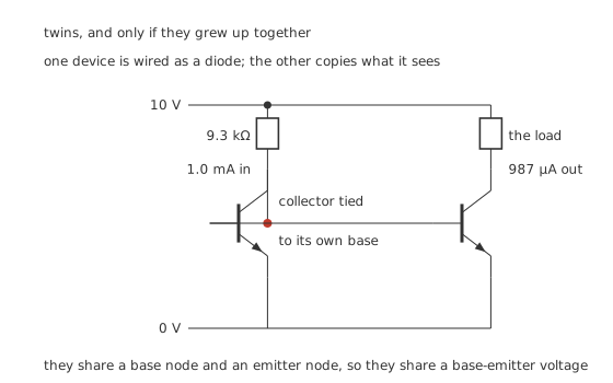
One device is wired as a diode; the other copies what it sees.
Worked example — Setting the reference and reading the copy
A resistor of 9.3 kΩ from a 10 V rail, with the diode-connected device holding about 0.70 V, sets a reference of 1.0 mA.
The output branch passes 987 µA, an error of -1.32 %.
That shortfall has one cause. Both base currents come out of the reference, not one, so the reference has to supply the copy plus two bases' worth. That is where the factor of the gain over the gain plus two comes from.
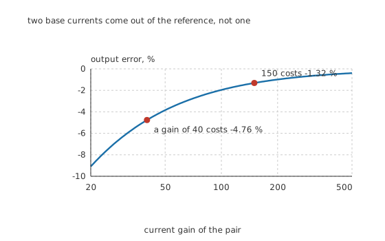
Two base currents come out of the reference, not one.
The connection everything depends on is the one that is easiest to draw wrongly: the diode-connected device's collector must actually be tied to its own base. Without that tie the left device has no base current path and nothing happens; tied to the wrong device it still looks plausible on a schematic and does not regulate.
Worked example — What the gain costs, and why it is the least of the problems
At the pair's nominal gain of 150 the base-current error is -1.32 %. Drop to a gain of 40 and it grows to -4.76 % — the output falling from 987 µA to 952 µA.
Both of those are small, one-sided and predictable, which makes this the easiest of the mirror's errors to live with.
Engineer
The error that actually decides the accuracy
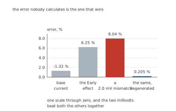
The error nobody calculates is the one that wins.
Worked example — Three errors, measured against each other
Base current, already worked out, costs -1.32 %.
The Early effect costs more. The output transistor's collector is not held anywhere in particular, and its current climbs as that voltage rises. With an Early voltage of 80 V, a 5.0 V output swing costs 6.25 %, and the output resistance behind it is 81.1 kΩ.
Mismatch costs most of all. A difference of 2.0 mV between the two junctions — far too small to measure with an ordinary meter, and easily produced by a couple of degrees of temperature difference across a board — puts the two currents 8.04 % apart, because the exponential turns millivolts into percentages.
That single figure is larger than the other two together, and it is the one that never appears in a first-pass calculation.
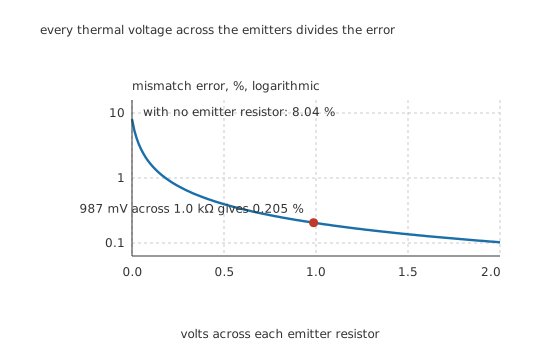
Every thermal voltage across the emitters divides the error.
Worked example — Emitter degeneration, and the two things it fixes at once
Put an equal resistor in each emitter. Now a device that tries to pass more current develops more voltage across its own resistor, which subtracts from its base-emitter voltage and pulls it back.
1.0 kΩ carrying 987 µA drops 987 mV, which against 25.9 mV is a factor of 39.2.
Mismatch error falls from 8.04 % to 0.205 % — and the output resistance rises by the same factor, from 81.1 kΩ to 3.18 MΩ, which fixes the Early error too.
One component, two of the three errors, and the same factor for both.
Professional
What it costs and what else can be done
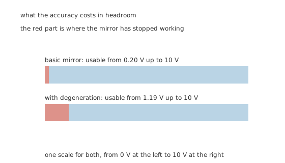
The red part is where the mirror has stopped working.
Worked example — The headroom the accuracy costs
A basic mirror stops behaving as a current source when its output transistor leaves the active region, at about 0.20 V. Everything above that is usable.
Add degeneration and the emitter resistor's 987 mV has to be found somewhere, so the output cannot fall below 1.19 V.
On a 10 V rail that is a modest price. On a three-volt rail with a signal that has to swing, it can be the reason the basic mirror is used despite its errors.
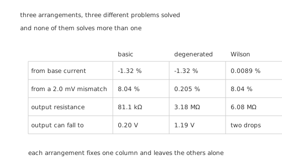
Three arrangements, three different problems solved.
Worked example — The Wilson arrangement, and what it does not fix
A third transistor can be arranged so that the base currents cancel almost exactly rather than being subtracted from the reference. The base-current error falls from -1.32 % to about 0.0089 %, and the output resistance rises to roughly 6.08 MΩ.
It does nothing at all about mismatch, which was the largest error to begin with.
That is the pattern worth carrying away: each arrangement attacks one column of the table and leaves the others where they were. Choosing between them means knowing which error your circuit actually cares about.
Four things about mirrors in real circuits
They are an integrated-circuit technique used discretely. On a chip the two devices are microns apart, made in the same step, at the same temperature — which is exactly the condition the arrangement assumes. Built from two separate parts on a board, none of that holds, and a matched dual transistor in one package is close to essential.
Thermal coupling is not optional. Two degrees between the devices produces a mismatch of the order this lesson works through. On a board they should be adjacent, in one package if possible, and away from anything that heats one and not the other.
The ratio need not be one. Making the output device twice the area of the reference gives twice the current; putting two output devices on one reference gives two matched copies. Both are routine on a chip, and the second is why a mirror often has several output branches.
They are how an amplifier gets its gain. A common-emitter stage's gain is limited by what its collector load can be, and a resistor large enough would drop the whole supply. A mirror in its place offers 3.18 MΩ of AC load while dropping almost no DC voltage, which is how integrated stages approach the intrinsic gain a resistor-loaded stage cannot.
Where this appears next
The differential pair uses a mirror twice over: once as the tail current source that makes the pair a pair, and once as the load that turns its two-sided output into one. Both uses depend on the accuracy this lesson works through, and both are why the mirror is worth a lesson of its own rather than a paragraph.
Common mistakes
- Leaving out the collector-to-base tie — without it the diode-connected device has no base current path and the mirror does nothing. It is one wire and it is the whole component.
- Assuming the copy equals the reference — two base currents come out of the reference, so the output is short by 1.32 % at a gain of 150 and 4.76 % at a gain of 40.
- Calculating the base-current error and stopping — a 2.0 mV junction mismatch costs 8.04 %, more than the base current and the Early effect together.
- Building one from two loose transistors — the arrangement assumes matched devices at the same temperature. Use a matched pair in one package, or expect the mismatch figure rather than the calculated one.
- Forgetting the compliance limit — the basic mirror needs 0.20 V at its output and the degenerated one 1.19 V, and below that it is a resistor rather than a current source.
- Reaching for a Wilson mirror to fix mismatch — it fixes the base-current error, to about 0.0089 %, and leaves mismatch exactly where it was.
Frequently asked questions
Why is one transistor wired with its collector to its base?
So that it settles at whatever base-emitter voltage carries the reference current. Nobody chooses that voltage — the device finds it. The second transistor then shares the same base and emitter nodes, so it has the same voltage across it and passes the same current.
Why is the output current slightly less than the reference?
Because both base currents are drawn from the reference, not one. That gives an output of the gain over the gain plus two: 987 µA for a 1.0 mA reference at a gain of 150, an error of −1.32 %, growing to −4.76 % at a gain of 40.
What limits a mirror's accuracy in practice?
Mismatch. A 2.0 mV difference between the junctions puts the currents 8.04 % apart, against 1.32 % from base current and 6.25 % from the Early effect over a 5.0 V swing. Two millivolts is a couple of degrees of temperature difference, or an ordinary manufacturing variation between two separate parts.
What does adding emitter resistors do?
Two things at once, by the same factor. Dropping 987 mV across 1.0 kΩ gives a factor of 39.2 against the thermal voltage, so the mismatch error falls from 8.04 % to 0.205 % and the output resistance rises from 81.1 kΩ to 3.18 MΩ. It costs headroom: the output can no longer fall below 1.19 V.
Can I build a mirror from two ordinary transistors?
It will work, and its accuracy will be set by how well those two happen to match and how similar their temperatures are. Since 2.0 mV costs 8.04 %, a matched pair in one package is close to essential for anything that has to be accurate, and thermal coupling matters as much as the initial match.