
Quick Answer
Biasing means setting the DC operating point a signal will swing around. The working method is a voltage divider holding the base at a fixed voltage and a resistor in the emitter turning that into a fixed current, which makes the collector current almost independent of the device's own current gain.
Intuition
The shelf the signal has to sit on
A signal that swings both ways needs somewhere to swing from. Put it at the bottom of its range and the downward half runs out of room; put it at the top and the upward half does. Somewhere in the middle is a shelf, and the job of biasing is to build that shelf and make sure it does not move.
The awkward part is what the shelf is built from. A transistor's current gain is not a number you are given — it is a number you are sold a range of, and two parts from one tape can differ by three to one. Build the shelf out of the gain and every board comes out at a different height.
So the trick is to build it out of something else. A voltage divider sets the base at a chosen voltage. A resistor in the emitter turns that voltage into a current: whatever the base sits at, minus the junction's own drop, appears across the emitter resistor, and the current follows from that alone.
Now the gain is not part of the calculation. It still decides how much base current is needed, but it no longer decides the answer. And when a warm day or a hot enclosure tries to push the current up, the emitter resistor pushes back on its own — more current there means more voltage there, which means less across the junction, which means less current.
The shelf builds itself, and then it holds itself in place.
Practitioner
The method, once, end to end
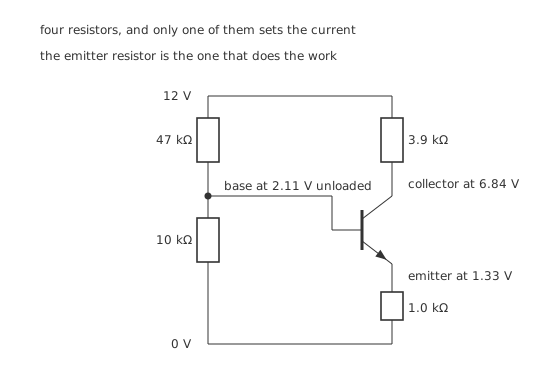
Four resistors, and only one of them sets the current.
Worked example — The whole method, executed once
Step one, find what the divider offers. 47 kΩ and 10 kΩ across 12 V give 2.11 V with nothing loading them, behind a source resistance of 8.25 kΩ.
Step two, take the junction's drop off it. Subtracting 0.70 V leaves what has to appear across the emitter resistor, less the small amount the base current drops across the divider's own resistance.
Step three, divide by the emitter resistor. 1.0 kΩ gives an emitter current of 1.33 mA, and the collector carries 1.32 mA of that, with 8.82 µA going into the base.
Step four, place the collector. 1.32 mA through 3.9 kΩ drops 5.16 V, so the collector sits at 6.84 V. The emitter is at 1.33 V, so the device holds 5.51 V.
Step five, check the result is usable. The device is comfortably in its active region and has 5.51 V of room for a signal to swing in.
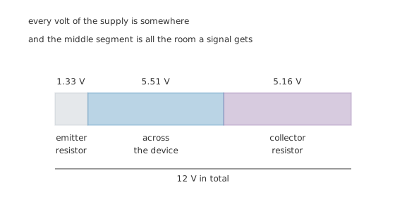
The middle segment is all the room a signal gets.
That last step is the one people skip. A bias calculation that produces a current but never checks where the collector landed has answered half the question, because a collector sitting at a volt has nowhere to swing down to and a collector sitting at the rail has nowhere to swing up to.
Engineer
Why the emitter resistor is doing all the work
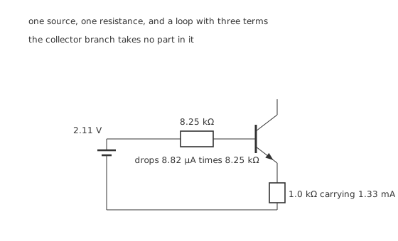
One source, one resistance, and a loop with three terms in it.
Replace the divider with its Thevenin equivalent and the base loop has exactly three things in it: the source, the junction, and the emitter resistor.
Worked example — Reading the loop, and seeing which term wins
Going round it, 2.11 V has to cover three drops: 8.82 µA across 8.25 kΩ, the junction's 0.70 V, and 1.33 V across the emitter resistor.
The first of those is the only one that involves the gain, and it comes to about seventy millivolts against a total of 2.11 V.
Halve the gain and that term doubles. It is still small, so the answer barely moves — and that, in one sentence, is why the arrangement works.
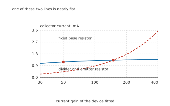
One of those two lines is nearly flat, and the flat one is the point.
Worked example — What a three-to-one spread of parts actually costs
Fit a device with a gain of 50 instead of 150 — a spread of 3.0, which is ordinary for one part number — and the collector current moves from 1.32 mA to 1.19 mA, a change of -10.4 %. The collector shifts to 6.17 V and the stage still works.
Do the same with a single base resistor sized for the same starting current, 1.28 MΩ from the rail. Now the base current is fixed and the collector current is simply the gain times it, so it falls to 441 µA — a change of -66.7 %.
The divider scheme is 6.41 times better against the same spread of parts, which is why almost every discrete amplifier in existence uses it.
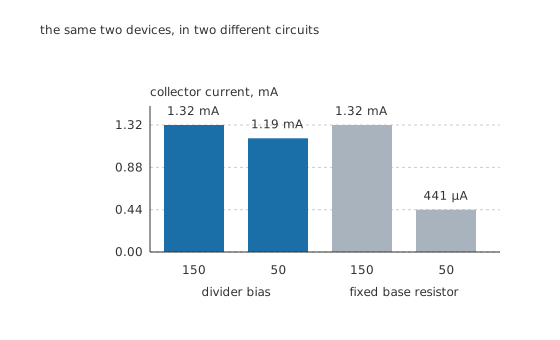
The same two transistors, in two different circuits.
There is one condition on all of this, and it is the divider's stiffness.
Worked example — How hard the divider has to be driven
The divider passes 211 µA on its own, against a base current of 8.82 µA — a ratio of 23.9.
The usual rule of thumb is at least ten, and the reason is visible in the Thevenin picture: making the divider stiffer lowers 8.25 kΩ, which shrinks the one term in the loop that the gain can move.
Stiffer is not free. The divider's current is drawn from the supply whether or not the stage is doing anything, and it also loads the signal source, so a divider ten times stiffer wastes ten times the standing current for a benefit that has already mostly been collected.
Professional
What the method does not fix
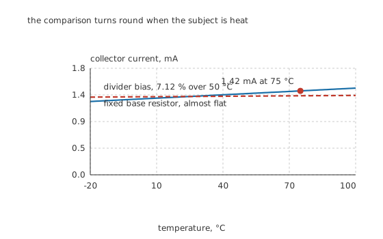
The comparison turns round completely when the subject is heat.
Worked example — The drift the emitter resistor cannot absorb
The junction's drop falls by about -2.0 mV per degree, so a 50 °C rise takes 0.70 V down to 600 mV.
The base is still being held at 2.11 V, so all hundred of those millivolts now appear across the emitter resistor instead. The current rises to 1.42 mA, a shift of 7.12 %.
The fixed-base circuit, by contrast, barely notices: the same hundred millivolts is a small change against the 12 V driving its 1.28 MΩ, so its current hardly moves.
The two schemes fail in opposite directions, and neither is simply better. Divider bias holds against the gain spread and drifts with temperature; fixed-base bias holds against temperature and collapses with the gain spread. Divider bias wins in practice because the gain spread is guaranteed and arrives on every board, whereas temperature drift of a few per cent is usually tolerable.
Four things worth deciding on purpose
How much voltage to spend on the emitter resistor. More of it means better stability and less headroom. One to two volts is the usual compromise, and 1.33 V here sits inside that. Below about half a volt the junction's own drop starts to dominate the loop and the scheme stops working; above about a fifth of the supply the signal has lost room it will miss.
Where to put the collector. Roughly midway between the emitter and the rail gives symmetric swing. 5.51 V against a rail of 12 V is close to that.
Whether the emitter resistor gets a bypass capacitor. For DC it always acts; for signals it can be shorted out by a capacitor to recover the gain it costs. That is an amplifier decision rather than a bias one, and it belongs to the common-emitter stage.
Whether the stage needs to hold better than a few per cent. If it does, the answer is not a better divider. It is a current mirror or another matched-junction arrangement, where the drift of one junction is cancelled by the drift of another.
Two failures this circuit produces when it is wrong
A collector sitting at the rail. Nothing is being drawn through the collector resistor, so either the base is not being driven — a divider resistor open, or the wrong way round — or the device is faulty. A voltmeter on the base settles it in seconds.
A collector sitting a few hundred millivolts above the emitter. The stage is saturated, which for a divider bias almost always means the divider is delivering too much base voltage. Check the ratio before suspecting the device, because the transistor's own regions are being visited exactly as they should be — just the wrong one.
Common mistakes
- Sizing a bias network from the current gain — gain spans three to one across parts sold under one number, and a fixed base resistor turns that straight into a 66.7 % swing in collector current. The divider scheme holds it to 10.4 %.
- Leaving the emitter resistor out — without it the base voltage sets a junction voltage rather than a current, and the exponential does the rest. The emitter resistor is the whole mechanism, not a refinement.
- Making the divider too soft — at a divider-to-base current ratio well under ten, the base current's drop across the divider's own 8.25 kΩ stops being negligible and the gain creeps back into the answer.
- Making the divider far stiffer than needed — it wastes standing current and loads the source, for a benefit that has already mostly been taken by the time the ratio reaches ten or twenty.
- Stopping at the current — a bias calculation that never checks where the collector landed has done half the job. Here it sits at 6.84 V with 5.51 V across the device, which is where the swing has to fit.
Frequently asked questions
Why does the emitter resistor make the bias independent of gain?
Because it converts the base's fixed voltage into a fixed current. Around the base loop, 2.11 V has to cover the base current's drop across 8.25 kΩ, the junction's 0.70 V and the voltage on the emitter resistor. Only the first term involves the gain and it is about seventy millivolts, so halving the gain barely moves the total.
How stiff does the divider need to be?
Ten times the base current is the usual rule and this network runs at 23.9. Stiffer lowers the 8.25 kΩ source resistance and so shrinks the one gain-dependent term in the loop, but the benefit flattens quickly while the wasted standing current does not.
Does divider bias fix temperature drift too?
No, and it is slightly worse than fixed-base bias in that respect. The junction's drop falls about 2.0 mV per degree, and all of that shift lands on the emitter resistor, so a 50 °C rise takes the collector current up 7.12 % to 1.42 mA. It is usually a price worth paying for the gain stability.
How much of the supply should the emitter resistor take?
Between about one and two volts on a supply like this — 1.33 V here. Much less and the junction's own 0.70 V starts to dominate the loop; much more and the signal loses swing it will need. The emitter resistor's voltage is the price of stability, paid in headroom.
Where should the collector sit?
Roughly midway between the emitter voltage and the rail, so a signal can swing equally both ways. Here 6.84 V on a 12 V rail with the emitter at 1.33 V leaves 5.51 V across the device, which is close to symmetric.