
A BJT sits in one of three regions. Cut-off means no base drive and almost no collector current. Active means the base current sets the collector current through the gain. Saturation means the load has taken over, the collector has fallen close to the emitter, and more base drive changes nothing.
Intuition
Idling, driving, and pressed against the kerb
What does a car pressed against a kerb tell you about its pedals? Idling in neutral, the engine turns and the car does not move. In gear on an open road, the pedal decides the speed and the relationship is straightforward. Nose against the kerb in gear, though, the pedal has stopped deciding anything: the kerb is deciding, and pressing harder only makes noise and heat.
A transistor has those same three conditions and the middle one is the only place the pedal analogy holds.
Cut-off is idling. No base current, so essentially no collector current, and the whole supply appears across the device because nothing is being dropped anywhere else.
Active is the open road. Base current arrives, the collector carries roughly the gain times that, and the collector voltage sits somewhere between the two extremes. This is the region every amplifier lives in.
Saturation is the kerb. The base is being driven harder than the load can absorb. The collector has already fallen as low as it goes, the current is fixed by the load rather than by the device, and more base drive is wasted.
The important part is that the transistor did not change between the three. The circuit around it did.
Practitioner
One circuit, three drives
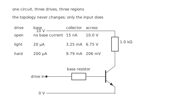
The topology is identical in all three rows; only the input changes.
Worked example — The three points, worked from the same load
With the drive open, only leakage flows — 15 nA for this device — so the 1.0 kΩ load drops almost nothing and the collector sits at 10.0 V.
Feed the base 20 µA. A gain of 150 would predict 3.00 mA; the device actually passes 3.25 mA, and the collector lands at 6.75 V.
Feed it 200 µA instead. Ten times the drive does not give ten times the current: the load allows 9.79 mA and no more, and the collector falls to 206 mV.
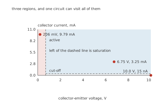
Three regions, and one circuit visiting all of them.
The boundary between active and saturation is not arbitrary. It sits at about 0.70 V, where the collector has fallen to the base's own voltage, because below that the collector junction stops being reverse biased and starts injecting backwards. Everything the active-region model says depends on that junction staying reverse biased, so the model simply stops applying on the other side of the line.
Engineer
The family of curves, and what each part of it means
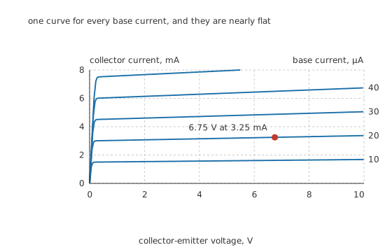
Each curve is one base current; the near-flat part is the active region.
Plot collector current against collector-emitter voltage, once for each base current, and the device's whole character is on one page. Every curve does the same two things: it climbs almost vertically out of the origin, then bends over and runs nearly flat.
The vertical part is saturation and it is narrow — a couple of hundred millivolts wide. The flat part is the active region, and the fact that it is nearly rather than exactly flat is the useful detail.
Worked example — Reading the tilt off the flat part
The flat sections are not level. Collector current climbs slowly with collector voltage because rising voltage widens the collector's depletion region, which thins the base, which raises the gain.
That tilt is described by an Early voltage, 80 V for this device. At 6.75 V it has lifted the collector current from the 3.00 mA the gain alone predicts to 3.25 mA.
The lift is 8.36 %, which is small enough to ignore in a bias calculation and much too large to ignore when the tilt itself is the thing you are measuring.
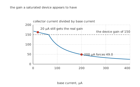
Past a certain drive, the ratio stops describing the device.
Worked example — Why a saturated device looks like a bad one
Divide the collector current by the base current at 200 µA and the answer is 49.0, against a device gain of 150.
Nothing has gone wrong with the transistor. The load allows only 9.79 mA, so the ratio simply records how much more base current was supplied than the circuit could use — here 3.06 times as much.
That ratio has a name, forced gain, and driving to a forced gain of about a fifth to a tenth of the real one is how a switch is designed on purpose.
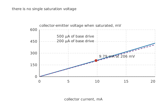
Neither curve is flat, so no single saturation voltage exists.
A saturation voltage is a property of an operating point, not of a part. Two things push it up: the junction has to give up more voltage to pass more current, and the collector's own bulk resistance — 20 Ω here — adds a drop straight in proportion to the current. Driving the base harder pushes the whole curve down but never flattens it, because the ohmic part does not care about base drive at all.
Professional
What each region costs, and how to stay out of the expensive one
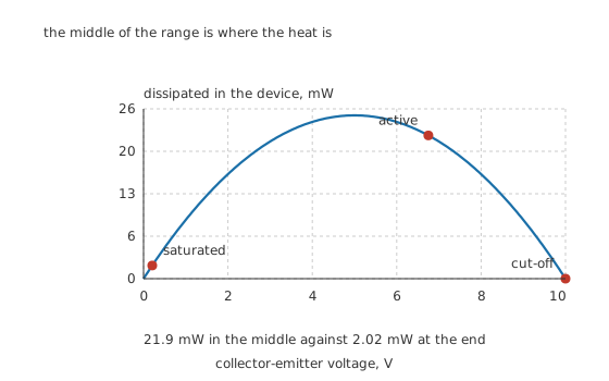
The heat lives in the middle, and both ends are nearly free.
Worked example — What the three points cost in heat
In cut-off, 10.0 V across 15 nA comes to 150 nW. Nothing worth thinking about.
Saturated, the current is large but the voltage is not: 206 mV across 9.79 mA is 2.02 mW.
In the active region both are substantial, and 6.75 V across 3.25 mA gives 21.9 mW — 10.9 times the saturated figure.
That ratio is the whole argument for switching rather than regulating. A device that spends its time at the ends of the load line dissipates a fraction of what the same device dissipates halfway along it, which is why a switching stage can control watts from a package that would burn up doing the same job linearly.
Four consequences worth carrying
An amplifier has to live where the heat is. There is no way to place a linear stage's operating point that avoids the parabola, because a signal has to be able to swing both ways from wherever it sits. Biasing is the discipline of choosing that point deliberately, and the load line is how the choice is drawn.
Saturation is slow to leave. Driving the base past what the load needs floods the base with charge that has to be removed before the collector voltage can rise again. The overdrive that guarantees a low saturation voltage is the same overdrive that delays turn-off, and the two have to be traded against each other rather than both maximised.
Cut-off is not quite zero. The 15 nA leakage here roughly doubles for every ten degrees of junction temperature, so a device that leaks nothing measurable on the bench may leak usefully more inside a hot enclosure. For a switch driving a high-impedance input that can matter.
Reverse-active exists and is almost never wanted. Forward biasing the collector junction and reverse biasing the emitter one puts the device in a fourth region with a gain of a few. It is what a wrongly wired transistor is doing, and it is the reason such a fault presents as poor performance rather than as an open circuit.
Where the boundaries actually get tested
Measure the collector voltage, not the current. In a working circuit the fastest way to identify the region is a voltmeter on the collector. Near the supply means cut-off, near the emitter means saturation, anywhere in between means active. Testing transistors out of circuit answers a different question.
Suspect saturation when a stage has no gain. A linear stage whose output refuses to move, sitting a few hundred millivolts above the emitter, is almost always saturated by a bias fault rather than a dead device. The meter reading that proves it takes a second.
Common mistakes
- Expecting collector current to follow the gain no matter how hard the base is driven — at 200 µA the load allows only 9.79 mA, so the apparent gain is 49.0 rather than 150. The load sets the ceiling.
- Quoting one saturation voltage for a part — it is 206 mV at 9.79 mA on this drive, and it rises with current because the collector's own 20 Ω of bulk resistance adds a proportional drop.
- Treating the active region's curves as flat — the Early voltage of 80 V tilts them, lifting this operating point 8.36 % above what the gain alone predicts.
- Driving a switch as hard as possible — the extra base charge that guarantees saturation is the same charge that has to be swept out before the device can turn off.
- Assuming cut-off means no current at all — leakage is 15 nA here and roughly doubles every ten degrees, which is enough to matter into a high-impedance load.
Parts used in this topic
Frequently asked questions
How do I tell which region a transistor in a working circuit is in?
Put a voltmeter on the collector. Near the supply rail means cut-off, a few hundred millivolts above the emitter means saturation, and anything in between means active. Here that is 10.0 V, 206 mV and 6.75 V for the three cases.
Why does the collector current keep climbing in the flat part of the curves?
Because raising the collector-emitter voltage widens the collector's depletion region, which eats into the base and makes it effectively thinner, which raises the gain. The Early voltage describes that slope — 80 V here, worth 8.36 % of extra collector current at this operating point.
What is forced gain and why is it lower than the real gain?
It is collector current divided by base current when the load, not the device, is setting the current. With 200 µA of base drive the load allows 9.79 mA, giving 49.0 against a device gain of 150. It is a measure of overdrive rather than of the transistor.
Why does the boundary between active and saturation sit near 0.7 V?
Because 0.70 V is roughly where the collector has fallen to the base's own voltage. Below it the collector junction stops being reverse biased and starts injecting carriers back into the base, which is exactly the condition the active-region model assumes will not happen.
Is it always better to saturate a transistor?
Only when it is doing switching. Saturated here costs 2.02 mW against 21.9 mW in the active region, a factor of 10.9, so a switch should certainly go there. But a saturated stage has no gain at all, and getting out of saturation is slower than getting in, so anything linear or fast has to stay clear of it.
Knowledge check
A transistor with a 1.0 kΩ load on a 10 V rail is given 20 µA of base drive. Where does it sit? (Show answer)
The same circuit is given 200 µA of base drive instead. What changes? (Show answer)
Why is there no single saturation voltage for a transistor? (Show answer)
Compare what the device dissipates in each of the three regions. (Show answer)
What decides the boundary between the active region and saturation? (Show answer)
One email a month from the bench
New circuits, lessons, part guides and calculators, on the first Sunday of each month.