
Quick Answer
A series RLC circuit is a resistance, an inductance and a capacitance in one loop. At its resonant frequency the inductive and capacitive reactances are equal and opposite, so they cancel and the impedance falls to the resistance alone. Current peaks there, and Q measures how sharp that peak is.
Intuition
The frequency where the coil and the capacitor cancel
Put a resistor, a coil and a capacitor in one loop, drive them from an alternating source, and the loop behaves differently at every frequency you try. Only one of the three parts holds the current back by a fixed amount. Capacitive reactance is large at low frequencies and shrinks as the frequency climbs; inductive reactance does the opposite, starting small and growing. Slide up the frequency axis and one of them is falling while the other rises.
Somewhere on that axis the two are the same size. That point matters because the coil and the capacitor do not simply oppose the current, they oppose it at opposite moments in the cycle. Whatever the coil is holding back, the capacitor is letting through, and the other way round. Equal in size and opposite in timing means they cancel, and the loop is left with nothing but its resistor.
That frequency is called resonance. The opposition the source feels drops to its lowest value anywhere on the axis, and the current, with only the resistance in its way, rises to its largest. What is easy to miss is that the voltages across the coil and the capacitor have not gone anywhere. Each of them can be many times larger than the source that produced them. They point in opposite directions at every instant, so the pair contributes nothing to what the terminals see, but both are genuinely there and a meter across either one will say so.
A circuit that responds strongly at one frequency and weakly at every other is how a radio picks one station out of the air, and how a filter throws away a hum nobody asked for.
Practitioner
Working out where it resonates and how sharply
Both reactances are calculated at whatever frequency the circuit is running at, and they move in opposite directions as that frequency changes.
Set the two equal to each other and the reactances themselves drop out of the algebra, leaving a frequency fixed by the component values alone:
The answer arrives in radians per second, so divide by 2π for hertz. Notice what is absent from that expression. The resistance decides how sharp the resonance is and has no say at all in where it sits.
At any frequency the impedance of the chain follows the usual series expression, with the two reactances entered as a difference:
At resonance the bracket is zero and the square root hands back the resistance on its own.
Worked example — Where the chain resonates, and what it looks like there
Take 10 Ω in series with 10 mH and 1.0 µF.
Their natural angular frequency is 10 krad/s, which as an ordinary frequency is 1.59 kHz.
At that frequency the coil contributes 100 Ω and the capacitor 100 Ω. The two are identical, so nothing of either survives the subtraction and the impedance is 10 Ω, the resistance and nothing else.
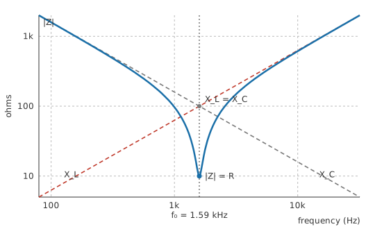
On logarithmic axes each reactance is a straight line, and the impedance curve hugs the capacitor below the crossing and the coil above it. Only in the narrow region where the two lines meet does the resistance get a look in, and the notch it opens there is deep enough to make the rest of the sweep look flat.
How narrow that notch is comes from the quality factor:
Bandwidth here means the span between the two frequencies at which the current has fallen to about seventy per cent of its peak value, which is half the power.
Worked example — How sharp the notch is
The same three parts give a Q of 10, so the bandwidth is 159 Hz.
Centred on 1.59 kHz, that puts the half-power edges near 1.51 kHz and 1.67 kHz. Outside that span the circuit has largely stopped responding.
Measuring it needs no more than a function generator swept across the range and an oscilloscope watching the voltage across the resistor. That voltage peaks at resonance, and the two frequencies where it has dropped to seventy per cent of the peak mark the bandwidth.
Engineer
Inside the cancellation
Series parts share one current, which makes that current the natural reference for everything else. The resistor's voltage rises and falls in step with it. The coil's voltage arrives a quarter of a cycle early and the capacitor's a quarter of a cycle late, leaving those two half a cycle apart: at every instant, one is as positive as the other is negative. Phasors sets out that bookkeeping properly. The consequence here is that the coil's voltage and the capacitor's voltage subtract, and at resonance they subtract to nothing.
What they do not do is get smaller. Each reactance is still substantial at resonance, and the shared current still flows through both. Ohm's law gives the voltage across each part with the reactance standing in for a resistance, which is legitimate as long as only magnitudes are wanted:
Worked example — What the source sees and what the parts see
Drive the same chain from 1.0 V at its resonant frequency. The impedance is the resistance alone, so the current is 100 mA.
That current develops 1.0 V across the resistor, which accounts for the whole of the source voltage.
It also develops 10 V across the coil and 10 V across the capacitor. Both stand well above the source, and because they are equal and opposite at every instant the terminals never see them.
The magnification factor is Q itself. At resonance the voltage across either reactive part is Q times the source voltage, and for this circuit that is the 10 the bandwidth calculation already produced. Q factor and bandwidth shows that this magnification, the ratio of centre frequency to bandwidth, and the energy stored per cycle divided by the energy lost are three readings of one number.
Safety
A one-volt generator producing ten volts across two components is a bench curiosity; the same multiplication driven from a wall socket is not. A series inductance and capacitance connected across the mains, on purpose or by accident, can develop several times the supply voltage across each part, well past the rating printed on either. The capacitor keeps that charge after the supply is removed. Every figure on this page came out of a calculation on signal-level components; treat a resonant circuit at mains potential as work governed by the practices in electrical safety.
Move off resonance and the cancellation degrades quickly, since the two reactances are travelling in opposite directions at once.
Worked example — One octave above
Double the frequency to 3.18 kHz. The coil's reactance doubles to 200 Ω while the capacitor's halves to 50 Ω.
What is left of the pair is no longer zero, and the impedance climbs to 150 Ω, more than an order of magnitude above its resonant value. The resistance has become almost irrelevant to the answer.
The same circuit read as a step response carries identical information in a different currency. Its damping ratio is 0.05, and Q is one over twice that, giving 10 and matching the reactance route exactly. Second-order transients handles the time-domain side; a lightly damped ring and a sharp resonance are one circuit described twice.
Conditions sit underneath all of this and are easy to leave unstated. One frequency at a time: a source carrying harmonics meets a different impedance at each of them, and a harmonic landing near the resonant frequency draws a current out of all proportion to its own amplitude. Steady state: these expressions describe the circuit after the switch-on transient has died, and that transient is itself the ringing the second-order treatment covers. Linear parts of constant value: a saturating core or a voltage-dependent ceramic shifts the resonant frequency while the circuit is running, and anything that bends the waveform out of a sinusoid leaves the phasor method with nothing to work on. And a series connection: the same three parts wired in parallel produce an impedance that peaks where this one dips, which is the subject of parallel RLC circuits.
Professional
The Q you get instead of the one you drew
The resistance in the worked examples above sits there as though somebody had fitted a resistor to provide it. In a real series resonant loop most of the loss arrives uninvited: the coil's winding resistance, the capacitor's equivalent series resistance, and whatever the source contributes through its own output impedance. Q responds to the total, and the total is rarely what the schematic shows.
That matters most where a design wants a high Q and fits no deliberate resistor at all.
Worked example — The same L and C with only the losses
Suppose the only resistance in the loop is 2.5 Ω of winding and dielectric loss.
Q rises to 40 and the bandwidth narrows to 39.8 Hz.
From the same source the resonant current is now 400 mA, and the voltage across the coil reaches 40 V.
The capacitor in that loop needs a voltage rating chosen against the magnified figure and not against the supply. Sizing it for the source is a reliable way to destroy a part in a circuit whose schematic looks entirely harmless, and the same caution applies to the coil's insulation.
Loss is frequency dependent, so a Q measured at one point does not transfer to another. Winding resistance climbs above its DC value as current crowds towards the conductor surface, core material absorbs energy of its own, and a capacitor's ESR moves with frequency too. A coil also carries self-capacitance, which resonates with the winding somewhere above the intended frequency; operate near that self-resonance and the part has stopped behaving as an inductor.
Tolerance moves the resonant frequency, though gently. Both component values sit under a square root, so a given percentage error in either shifts the frequency by roughly half as much, and errors in opposite directions partly cancel. Q is far less forgiving, since it hangs on a resistance nobody specified. A tuned circuit assembled from catalogue parts lands close to its intended frequency and some distance from its intended Q. Adjustable cores and trimmer capacitors are the usual answer, and they are fitted to correct the frequency rather than the Q.
Where the loop is driven hard, core saturation is the failure worth anticipating. Resonant current is large by design, and an inductance that collapses at peak current detunes the circuit at the moment it is working hardest.
An LCR meter reports L, C and a loss figure at a chosen frequency, and Q follows from those. Sweeping the assembled loop answers the question more directly, because it includes every loss actually present, including the ones a component-level meter never sees. Watch the loading while you do it: a probe across the capacitor adds capacitance to the very circuit it is meant to be reporting on.
Series resonance is put to work wherever a low impedance at one frequency is wanted alongside a high impedance everywhere else. A trap filter shunts one unwanted frequency to ground through it; a receiver front end tunes with it; the resonant sections inside band-pass and band-stop filters are built on it. Where no coil and capacitor together can reach the Q a design needs, a quartz crystal is a mechanical series resonator whose Q runs orders of magnitude higher, and a circuit treats it under this same model.
Common mistakes
- Expecting the resistance to move the resonant frequency — it does not. L and C fix where the peak sits; R only decides how sharp it is and how much current flows there.
- Rating the capacitor for the supply voltage — at resonance it carries Q times the source. A modest generator can put hundreds of volts across a part chosen for tens.
- Adding the two reactances instead of subtracting them — they act half a cycle apart, so the impedance expression takes their difference. Adding turns a cancelling pair into a large opposition that is not present.
- Reading the parallel expression for Q onto a series circuit — more resistance lowers Q in series and raises it in parallel, so picking the wrong one sends the answer the wrong way.
- Trusting the drawn resistor to set Q — in a high-Q loop the coil's winding resistance and the capacitor's ESR usually contribute more, and neither appears on the schematic.
- Probing the capacitor to find the resonant frequency — the probe's capacitance joins the tuned circuit and shifts the figure it is supposed to be measuring.
Frequently asked questions
What happens at resonance in a series RLC circuit?
The inductive and capacitive reactances become equal and cancel, so the resistance is the only opposition left. Impedance falls to its minimum and the current rises to its maximum, arriving in phase with the source voltage because nothing reactive is left to delay it.
Why is the voltage across the capacitor larger than the supply?
Its reactance is still large at resonance even though the pair cancels, and the resonant current is large as well. Their product is the capacitor's voltage, and it works out at Q times the source. The coil holds an equal and opposite voltage at the same instant, so the two never reach the terminals together.
Does the resistor change the resonant frequency?
No. The inductance and the capacitance fix it between them. Resistance sets the Q, the bandwidth, the current at the peak and the depth of the impedance dip, and leaves the frequency exactly where it was.
How do I raise the Q of a series resonant circuit?
Lower the total loop resistance, or raise the ratio of inductance to capacitance. More inductance and less capacitance at the same frequency means more reactance at resonance and therefore more Q for a given resistance. In practice the coil sets the ceiling.
How does a series RLC differ from a parallel one at resonance?
They share a resonant frequency and behave oppositely at it. The series circuit shows minimum impedance and maximum current; the parallel circuit shows maximum impedance and minimum line current. Resistance also works in opposite directions on their Q values.