
Quick Answer
A seven-segment display is seven LEDs arranged as bars, with one end of all of them joined into a common pin. Lighting the right combination makes any digit. Multiple digits are usually multiplexed, which cuts the pin count sharply and raises the peak current in exact proportion.
Intuition
Ten digits from seven matchsticks
Lay seven matchsticks out as a figure eight and you can make every digit from nought to nine by taking some of them away. Two matchsticks make a one, three make a seven, all seven make an eight. Nobody has to build ten separate shapes, and nobody has to remember what a five looks like: there is a table saying which sticks to leave in place.
A seven-segment display is that arrangement in LEDs. Seven bars, each one a light-emitting diode, laid out as the figure eight. Light the right subset and the digit appears. Most parts add an eighth, the decimal point, which is why the connection count is eight rather than seven.
The convenience of it is that a digit stops being a shape problem and becomes a lookup. Any circuit that can turn eight outputs on and off can display any digit, and the mapping is a table small enough to write out on one page.
The awkwardness is that eight outputs per digit adds up quickly. A four-digit display is thirty-two connections, and very few controllers have thirty-two spare pins for a readout. The solution is to light one digit at a time, fast enough that the eye does not notice, which cuts the connections dramatically and raises the current through each segment by exactly the factor you saved.
Practitioner
The part, and how it is wired inside
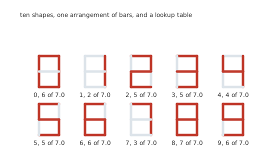
Ten shapes, one arrangement of bars, and a lookup table.
The segments have standard letters. The top bar is a, then b and c down the right side, d along the bottom, e and f up the left, and g across the middle. A one is b and c; an eight is all 7.0; with the decimal point a part has 8.0 LEDs in it.
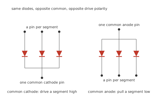
Same diodes, opposite common, opposite drive polarity.
A common-cathode part joins all the cathodes to one pin. Hold that pin low and drive a segment's pin high to light it.
A common-anode part joins all the anodes instead. Hold that pin high and pull a segment's pin low.
The diodes point the same way in both; only which end is commoned differs. The two are not interchangeable and a display driven with the wrong polarity simply never lights, which is a five-minute fault that has cost people an afternoon.
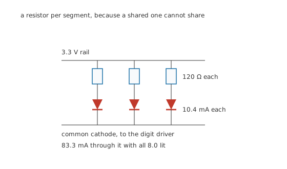
A resistor per segment, because a shared one cannot share.
Worked example — Sizing the segment resistors
On a 3.3 V rail with the LED at 2.05 V, a target of 10 mA per segment computes to 125 Ω, so 120 Ω is chosen and each segment carries 10.4 mA.
With all 8.0 lit, the common pin carries 83.3 mA, which is what the driver on that pin has to survive.
Across 4.0 digits driven statically that is 333 mA and 1.10 W from the supply.
Every segment needs its own resistor, for the reason LED drive circuits works through: LEDs sharing a resistor divide the current by their forward voltages rather than equally, so the brightness would depend on which digit was displayed.
Engineer
Multiplexing
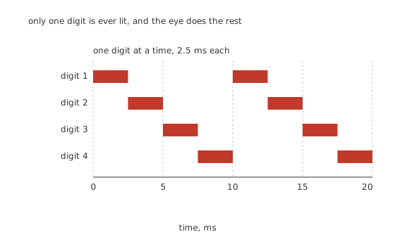
Only one digit is ever lit, and the eye does the rest.
Instead of driving every digit continuously, wire all the digits' segment pins together and give each digit its own common pin. Then light one digit at a time, cycling fast enough that the eye integrates the result.
Worked example — What the scan looks like
At a frame rate of 100 Hz, whose period is 10 ms, each of the 4.0 digits gets 2.5 ms.
That is a duty of 0.25 per digit, and the segment drivers switch at 400 Hz.
The wiring falls from 32 driver pins to 12, a saving of 20, and from 32 resistors to 8.0.
The brightness has to be made up somewhere, and it is made up in current.
Worked example — Sizing the multiplexed resistors
To match the static brightness the peak has to be the average divided by the duty, which is 41.7 mA.
At that current the LED's own drop rises. From 2.05 V at 10.4 mA, with an ideality factor of 2.0 and a thermal voltage of 25.85 mV at 300 K, it becomes 2.12 V, so the resistor computes to 28.3 Ω and 27 Ω is chosen.
The drop and the current depend on each other, so the real operating point is found by iterating: it settles at 2.124 V and 43.6 mA, giving an average of 10.9 mA, a shade brighter than the static design.
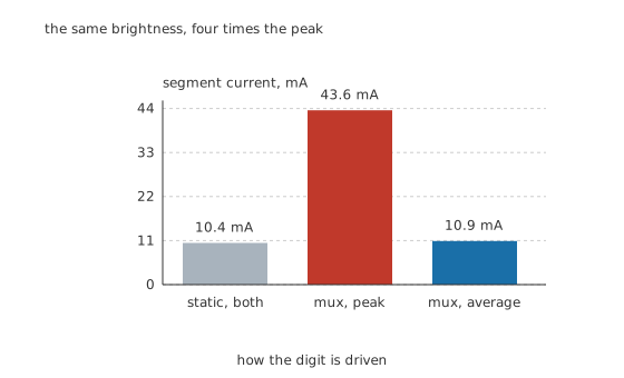
The same brightness, four times the peak.
That peak is the number that matters. The common pin now carries 348 mA while its digit is lit, which is beyond what a controller pin can source and needs a transistor. And the display's own peak-current rating has to cover it, which is why displays are specified with a peak rating and a duty cycle rather than only a continuous one.
Professional
Getting a multiplexed display right
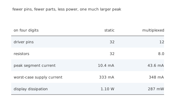
Fewer pins, fewer parts, less power, one much larger peak.
The supply current falls, which surprises people. Statically all four digits draw 333 mA at once. Multiplexed, only one digit is ever lit, so the worst case is 348 mA and the average dissipation falls from 1.10 W to 287 mW. Multiplexing saves pins and peak supply current; what it costs is peak segment current and complexity.
Four things that go wrong
Ghosting. If the segment pattern changes before the previous digit's common driver has fully turned off, the new pattern appears faintly on the old digit. The fix is to blank the digit drivers, change the segments, then re-enable, and it costs a few microseconds of duty.
Flicker. Below roughly fifty frames a second the display visibly shimmers, and above that a camera or a moving eye can still see it. 100 Hz is comfortable for a static viewer; a display that will be photographed or seen in a vehicle wants several hundred.
Uneven brightness. A digit displaying a one lights two segments and a digit displaying an eight lights all seven. If the digit driver has any resistance, the eight sags and looks dimmer. Constant-current segment drivers remove this entirely and are why dedicated display driver chips exist.
Forgetting the digit driver. A controller pin sourcing or sinking 348 mA is beyond every ordinary part. Each digit's common pin needs a transistor, and its base or gate drive has to be fast enough not to smear the scan.
When not to multiplex
One or two digits. The pin saving is small and the complexity is not. Two digits statically is sixteen pins, which a shift register handles without any timing at all.
When the software cannot guarantee the scan. A multiplexed display is only lit while the code is refreshing it. A controller that stalls leaves one digit lit continuously at four times its rated current, which destroys it in seconds. Anything with an uncertain scheduler wants a driver chip that holds the pattern itself.
When brightness matters more than pins. The peak current a multiplexed display needs eventually runs into the part's own rating, and past about eight digits the duty is low enough that the required peak is not achievable. Beyond that the answer is more driver chips rather than a longer scan.
The relatives
Fourteen-segment and sixteen-segment displays add diagonals so that letters are legible, and everything here applies unchanged with more segments.
Dot-matrix displays are the same idea taken further: rows and columns multiplexed against each other, so an eight-by-eight matrix needs sixteen connections for sixty-four LEDs. The peak-current arithmetic is the same, with a duty of one in eight instead of one in four.
Common mistakes
- Buying the wrong common type — a common-anode part driven as common-cathode never lights, and the two look identical from outside.
- Sharing one resistor between segments — the segments divide the current by their forward voltages, so a digit's brightness changes with which digit it is.
- Driving the common pin from a controller — 348 mA while the digit is lit is far beyond any controller pin, and every digit needs a transistor.
- Using the display's continuous rating for a multiplexed design — the peak is 43.6 mA against a static 10.4 mA, and it is the peak rating with its stated duty that applies.
- Letting the scan stall — a multiplexed display that stops being refreshed leaves one digit lit at four times its rated current, and it does not survive long.
Frequently asked questions
What is the difference between common anode and common cathode?
Which end of the seven LEDs is joined to the single shared pin. On a common-cathode part the shared pin is held low and each segment is driven high to light it; on a common-anode part the shared pin is held high and each segment is pulled low. They are not interchangeable and a display driven the wrong way simply stays dark.
Why does each segment need its own resistor?
Because LEDs sharing one resistor divide the current between them according to their forward voltages rather than equally. The brightness would then depend on how many segments were lit, so a one would be much brighter than an eight.
What does multiplexing a display actually do?
It lights one digit at a time, fast enough that the eye sees them all lit. Four digits scanned at 100 Hz each get 2.5 ms in every 10 ms. That cuts the driver pins from 32 to 12 and the resistors from 32 to 8, and raises the peak segment current by the reciprocal of the duty.
How much peak current does a multiplexed segment need?
The average brightness you want, divided by the duty cycle. Here 10.4 mA average at a duty of 0.25 needs about 43.6 mA while the digit is lit, and the LED's own forward voltage rises at that current so the resistor has to be recalculated rather than simply divided.
Why does my multiplexed display show faint ghosts of the previous digit?
Because the segment pattern is changing before the previous digit's common driver has finished turning off, so the new pattern briefly appears on the old digit. Blank the digit drivers first, change the segments, then re-enable, and the ghosting disappears.