
Quick Answer
A breadboard joins holes into fixed groups without solder: five sockets in a strip form one node, and each power rail runs the length of the board as another. That makes a circuit quick to build and quick to change. It also adds contact resistance at every joint and a supply loop far larger than a printed board would have.
Intuition
A strip of five sockets
A breadboard is a plastic block full of holes with spring clips underneath, and the clips are what you are actually wiring to. Five holes in a line share one clip. Push two component leads into any two of those five and they are connected, without solder and without a wire between them. Five chairs at one table: whichever chair you take, you are sitting at the same table as everyone else.
The rest of the board follows from that. Short strips run in two banks, and a channel down the middle separates them so a dual-in-line package can straddle it with each row of pins landing in strips of its own. Along the outside edges run the rails, and a rail is one clip as well, except that it stretches the whole length of the board instead of five holes.
The dimensions are not arbitrary. Holes sit on a 2.54 mm pitch, the 0.1 inch grid the entire through-hole component world is built to, so a resistor's lead spacing, an integrated circuit's pin spacing and the board's holes all agree without anyone having to arrange it. A strip runs 10.16 mm from its first socket to its fifth, all 5 of them one node. The channel is 7.62 mm across. Count the strips in the segment drawn below, add the rails, and there are 36 separate nodes to wire between.
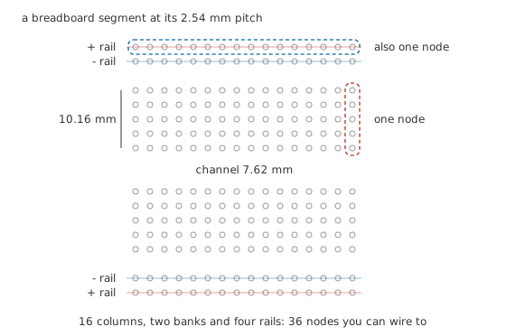
The holes you can see are not the connections. The clips underneath are, and they run the short way in the banks and the long way in the rails.
Practitioner
Laying out a circuit you can still read
A board rewards a habit or two and punishes improvisation. The layout worth having is the one you can still trace three days later with a meter in your hand.
- Power first. Bring the supply to the rails before anything else goes in, and settle which rail is which. Most boards print a red line and a blue one along the edges; use them the same way every time.
- Chips across the channel. Seat every dual-in-line package straddling the centre gap, pin 1 at the same end each time, so a probe never has to guess.
- Short jumpers, flat to the board. A long wire arching over the circuit is awkward to trace and behaves as an aerial. Cut solid-core wire to length instead of reaching for a pre-formed lead of the wrong size.
- One node, one strip. Where a node needs more connections than a strip has holes, run a jumper to a second strip rather than forcing two leads into one hole.
- Check whether the rails split. Many boards break each rail into halves partway along, with a gap in the printed line as the only warning. A jumper across that gap costs nothing.
- Leave room to probe. Every node you expect to measure wants one hole in its strip kept free for a probe tip.
None of that touches the electrical question, which is whether the rails carry what the circuit draws. They do, up to a point, and the point is worth working out rather than guessing at.
Take a load some way along the rail from where the supply enters. Three resistances sit in that path: the contact where the supply lead grips its clip, the rail's own metal between there and the load, and the contact at the far end where the load lead grips. Call one contact 12 mΩ and the strip 3.0 mΩ per socket of run. Both are illustrative figures for the arithmetic below rather than a specification for any board you can buy.
Worked example — What the rail run costs
A load sits 18 sockets along a power rail from the supply's entry point, drawing 240 mA.
The strip between the two leads contributes 54 mΩ, and with a contact at each end the path from lead to lead is 78 mΩ.
That costs 18.7 mV, of which 2.88 mV sits in each contact alone. A rail set to 5.0 V reaches the far socket as 4.981 V.
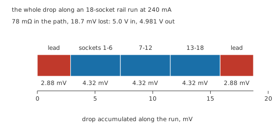
Steady current is the easy case, and this is the easy case drawn.
For most bench work that settles it. A logic chip drawing the same average current in short bursts asks a different question, and Layer 4 answers that one.
Safety
Worth naming before the board fills up: solderless boards are bench tools. The clips are small, the plastic web between neighbouring strips is thin, and a breadboard carries no insulation or creepage specification you can point at. Mains wiring, high-energy battery packs and anything where a jumper working loose would matter all belong on something built for the job. The practices for work above bench voltages are set out in electrical safety fundamentals.
Engineer
The parts the board adds to your circuit
Every joint is a resistance
A soldered joint is a metal-to-metal bond. A breadboard contact is a spring pressing on a lead, and that pressure is the entire connection. It works well — and it does not work perfectly.
A part with one lead in one strip and its other lead in a second strip meets two contacts, so 24 mΩ before the part itself. A jumper between two strips meets two more, plus its own wire. Copper is the easy part to be exact about: at a resistivity of 16.8 nΩ·m, a 100 mm length of 0.644 mm solid wire has a cross-section of 0.326 square millimetres, and
gives 5.16 mΩ for the wire. The jumper link end to end is 29.16 mΩ, and the wire is the smaller half of it. Soldering the same wire at both ends, at an illustrative 1.5 mΩ per joint, brings the link to 8.16 mΩ. Soldering basics covers what makes a joint that good.
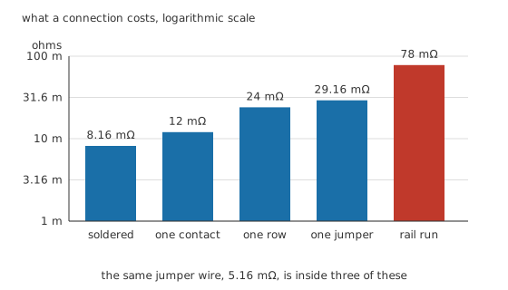
A logarithmic axis, so no bar height here stands in proportion to any other. The wire is barely involved — the contacts do all of it.
At the currents most prototypes draw, none of that is a problem. The problem is that a contact does not stay at 12 mΩ forever. Clips lose their spring, plating oxidises, and a hole that has taken a component lead too thick for it never grips a thin one properly again. Suppose one contact in the supply path has drifted to 1.20 Ω.
At the same 240 mA that one contact drops 288 mV and dissipates 69.1 mW, both of them arithmetic on the resistance rather than a measurement. There is the intermittent breadboard fault in a line — nothing is broken, everything is connected, and a quarter of a volt has gone somewhere you cannot see. Press on a jumper and the circuit recovers, which is a diagnosis, not a repair.
The strip next door
Any two pieces of metal a few millimetres apart, running parallel for a centimetre, make a capacitor. A small one — the figure this lesson works with is 3.5 pF between one strip and its neighbour, illustrative rather than measured. A strip has a neighbour on each side, so
puts 7.0 pF on every strip before anything is plugged into it. Spread one signal across 4 strips, which a circuit with a few jumpers does without trying, and the node carries 28.0 pF. Let the same signal sprawl over 8 and it carries 56.0 pF.
Whether that matters depends on what drives it. A source with 50 Ω of output impedance sees
which is 1.40 ns for the tidy net and 2.80 ns for the sprawling one, and
turns those into 3.08 ns and 6.16 ns of rise time contributed by the board alone.
Put a real edge through it. Model the driver's own transition as a straight ramp reaching the rail in 10.0 ns, so its 10 to 90 per cent time is the 8.0 ns a datasheet would quote. Solve that ramp against the row capacitance and the edge arrives at 8.39 ns across the tidy net and at 10.05 ns across the sprawling one. The first is a rounding error. The second has lost a fifth of the edge to the board itself.
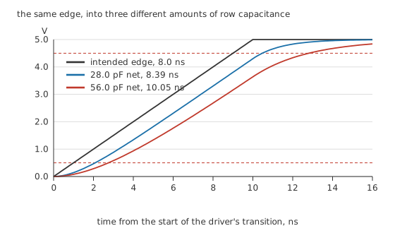
Same driver, same edge, three different amounts of strip hanging off it.
Seen in the frequency domain, the same capacitance is a low-pass filter nobody designed:
113.7 MHz for the tidy net, 56.84 MHz for the sprawling one. Both sit far above anything a beginner's prototype runs at, and that is the honest reason breadboards work as well as they do. What they do not sit far above is the spectrum inside a fast edge, which a logic family puts there whether the clock is fast or not. Pulse response and rise time works out the relation between an edge and the bandwidth it needs.
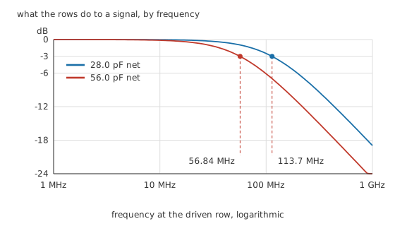
The corner moves down every time a signal picks up another strip.
Professional
Loop area, and when to stop breadboarding
Layers 2 and 3 both treated the supply as a pair of conductors with resistance. At the instant a chip switches, it is something else.
Current returns. Whatever leaves the positive rail comes back along the negative one, and the path between them encloses an area. That area has inductance. The figure this lesson uses for it is 1.0 nH/mm of loop, a rule of thumb rather than a specification, and the arithmetic below inherits that status.
Put a decoupling capacitor 2 columns from the chip and the loop out to it and back measures 25.40 mm, worth 25.4 nH. Park the same part at the end of the rail, 24 columns away, and the loop becomes 137.2 mm and 137.2 nH.
Inductance only sends a bill when the current changes. Switch 240 mA in the 8.0 ns edge from Layer 3 and the rate is 30.0 MA/s. The short loop then develops 762 mV and the long one 4.11 V, both of them from the loop length and the stated inductance per millimetre rather than from an instrument. On a 5.0 V rail the second figure is more than four fifths of the supply, which in practice means the rail sags and rings rather than holding while the arithmetic asks for the impossible. Every chip sharing that rail sees it.
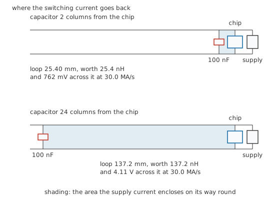
The shading is the area the return current has to go round. Only the capacitor moved between the two panels.
The capacitor and its loop are also a series resonant circuit, which is the part that catches people out. With 100 nF across the rails,
gives 19.84 Mrad/s for the short loop, or 3.16 MHz in ordinary frequency, against 1.36 MHz for the long one. Above its own resonance the pairing behaves as an inductor, so the far placement gives up at less than half the frequency the near one reaches. Placement beats capacitance here — and placement is what a breadboard gives you least of.
The board is honest about DC and about audio, and honest enough about a few megahertz. It stops being honest when a circuit contains an edge fast enough to notice the row capacitance, or a supply loop wide enough to notice the switching current. A node quiet enough to notice the strip next door is the third case, and that one catches analogue work rather than digital. Radio circuits, switching regulators, crystal oscillators and analogue front ends hunting microvolts all want a soldered prototype, on stripboard or on a plated-through board where the return path can run under the signal instead of around the outside of it.
There is a measurement trap folded into all of this. A scope probe on a breadboard node adds its own capacitance to the strip's, so a marginal circuit gets worse the moment you look at it, and a circuit that only behaves with the probe attached has told you something. Oscilloscope probes and 10x attenuation has the arithmetic for that, and using a multimeter covers the DC half of the same job.
One habit repays itself constantly and costs nothing: photograph the board before pulling it apart. A prototype that worked last month always contains one jumper you cannot account for, and a phone picture beats the schematic you meant to draw.
Common mistakes
- Assuming the schematic is what the board does. Two leads sharing a strip are connected whether you meant them to be or not, and a part bridged across a single strip is short-circuited by its own row.
- Building the circuit before the rails. Power and ground going in last means every jumper afterwards is routed around them, and the supply loop ends up as long as the board.
- Trusting a socket that has taken a thick lead. Transistor tabs, thick resistor leads and stripped mains-flex strands all stretch a clip permanently, and the next thin lead in that hole is an intermittent connection.
- Blaming the circuit for a contact. A prototype that works when you press on it has a mechanical fault, not a design fault, and the cure is a different hole rather than a different resistor.
- Decoupling at the end of the rail. A capacitor across the rails is doing nothing useful for a chip at the other end of the board, because the loop it closes is longer than the one it was meant to shorten.
Frequently asked questions
How many holes are connected together on a breadboard?
Five, in each strip of the two main banks, running the short way across the board. The rails along the edges are separate nodes that run the long way, and many boards split each rail into two halves partway along with only a gap in the printed line to say so.
Why does my breadboard circuit work sometimes?
Almost always a contact rather than a component. Clips lose their grip, plating oxidises, and a hole stretched by a thick lead never holds a thin one again. Move the suspect connection to a fresh strip before changing anything electrical.
What is the fastest signal a breadboard can handle?
There is no single number, because it depends on how far the signal sprawls and what drives it. As a working rule, digital circuits below a few megahertz are comfortable, fast logic edges are already being softened, and anything above tens of megahertz is being measured on the board rather than through it.
Can I use a breadboard for mains voltages?
No. The clips are small, the plastic between neighbouring strips is thin, and a solderless board carries no insulation rating you can look up. Keep it to bench supplies and low-energy batteries.
Where should the decoupling capacitor go?
In the two strips closest to the chip's supply and ground pins, with the shortest leads you can leave on it. The loop from capacitor to chip and back is what the capacitor is fighting, and moving the part a few columns multiplies that loop several times over.