
Quick Answer
Logic families differ in what they charge you for. One kind draws a steady current whatever it is doing; the other draws almost nothing standing still and pays per transition instead. That difference sets the power, the supply range, how many inputs one output feeds, and which end of a wire has to be shifted.
Intuition
Rent, or per transition
A relay race is decided in the changeover box as often as on the track. The incoming runner is going full speed and the outgoing one is standing still, and the baton has to move between them inside a marked twenty metres. Two very fast people can lose to two slower ones who practised the handover.
What makes it hard is that the two runners have different requirements at the moment of contact. The outgoing runner needs to be moving before the baton arrives; the incoming one needs to be close enough to place it. Neither requirement is difficult alone.
Logic families meet in the same box. Each one is internally consistent — its outputs produce what its inputs demand, with room to spare — and the interesting questions are all at the handover: what one family's output can supply, what the other family's input asks for, and whether the answer arrives in time.
Where the thresholds are is the voltage half of that question, and that lesson owns it. This one is about everything else: current, power, speed under load, and how much rail each family needs.
Two invented families carry the argument and neither is any real one. A switching family that draws almost nothing standing still, and a standing family that draws a steady current whatever it does. Every number attached to them is made up.
Practitioner
The two ways a family spends its supply
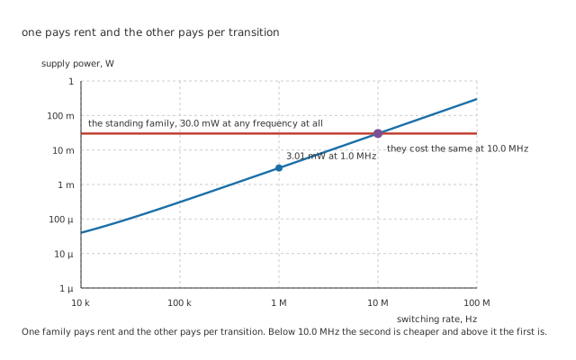
One family pays rent and the other pays per transition.
The standing family's current is a property of its circuits: transistors are biased on, and the current flows whether anything changes or not. The switching family's transistors are off in both stable states, and current only flows while something is moving from one to the other.
Worked example — What one transition costs
Every time an output changes, it has to move whatever capacitance is hanging on it — 15 pF here — between ground and the rail and back.
Charging 15 pF to 5.0 V takes the supply 375 µW at 1.0 MHz, and 8 outputs doing it come to 3.00 mW.
Add the 10.0 µW that 2.0 µA of standing current costs, and the switching family comes to 3.01 mW — of which 99.7 % is the transitions — against the standing family's 30.0 mW: a factor of 9.97.
The factor in that formula is worth a sentence, because it is not the half everyone expects. Charging a capacitor to a rail always wastes as much in the resistance doing the charging as it stores in the capacitor, so the supply gives up the whole product rather than half of it. Discharging then throws the stored half away too. Over a full cycle the supply has delivered the capacitance times the voltage squared, and none of it is left anywhere.
And why the advantage runs out
Worked example — Where the two lines meet
The switching family's cost climbs with frequency and the standing family's does not.
They meet where 8 outputs of switching cost the whole 30.0 mW, which is 10.0 MHz.
At that rate the transitions alone come to 30.0 mW. Below it the switching family is cheaper, and at 1.0 MHz it is cheaper by 9.97 times; above it, the family that pays rent is the economical one — and it is the faster of the two anyway, at 6.0 ns against 9.0 ns.
Engineer
The rail, the input, and the two ways to run out
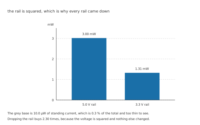
The grey standing slice is 10.0 µW in both and is too thin to see.
The voltage in that formula is squared, and that one exponent explains most of what has happened to logic supplies over four decades.
Worked example — What a lower rail buys
The same 8 outputs switching the same 15 pF at the same 1.0 MHz cost 3.00 mW on 5.0 V.
On 3.3 V they cost 1.31 mW.
That is 2.30 times less from a rail only about one and a half times lower, and nothing else in the circuit changed.
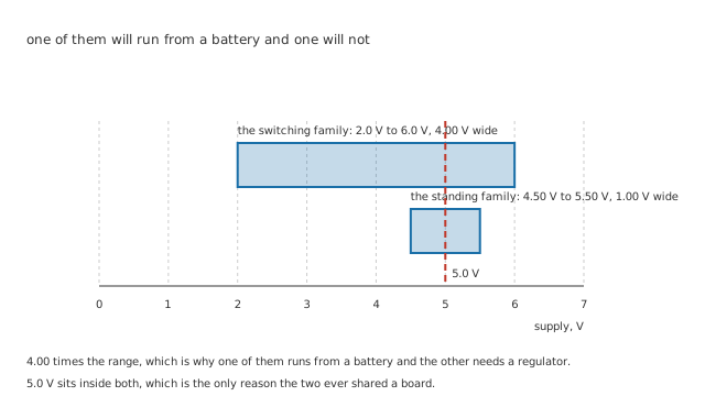
4.00 times the range, and 5.0 V sits inside both.
The families differ on how much rail they will take at all. The switching one works over 4.00 V and the standing one over 1.00 V, a factor of 4.00. That is the difference between a part that runs from a battery as it discharges and a part that needs a regulator in front of it.
What one input costs the thing driving it
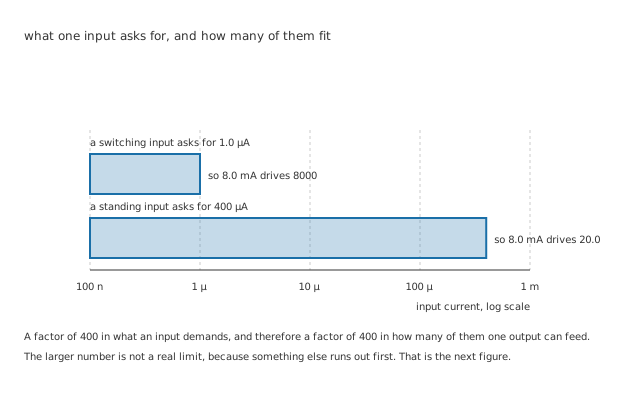
The larger fan-out number is not a real limit, because something else runs out first.
Worked example — Fan-out, by the current rule
An output that can sink 8.0 mA can feed inputs until that current is used up.
A standing family's input demands 400 µA, so one output feeds 20.0 of them.
A switching family's input leaks 1.0 µA, which is 400 times less and gives 8000 — a number nobody has ever built, because the current rule stopped being the binding one.
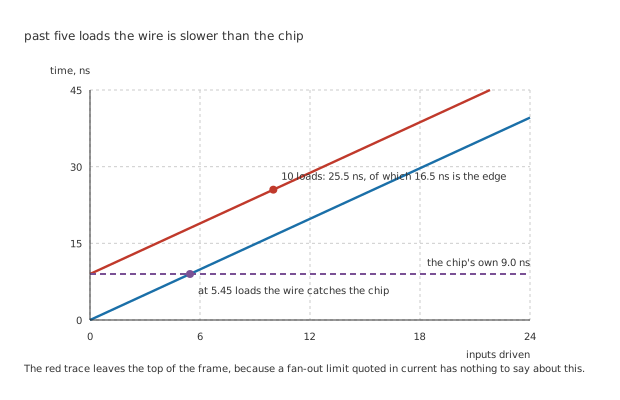
The red trace leaves the top of the frame, because a fan-out limit quoted in current has nothing to say about this.
Worked example — Fan-out, by the timing rule
Every input that leaks nothing still presents 15 pF of capacitance, and 10 of them come to 150 pF.
The driving output's 50 Ω charging that is 7.50 ns, so the edge takes 16.5 ns.
Added to the part's own 9.0 ns that is 25.5 ns, of which 64.7 % is the wire rather than the chip — and the edge alone equals the chip's delay at only 5.45 loads.
Professional
The changeover
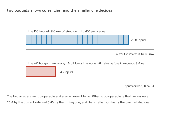
The two axes are not comparable and are not meant to be. What is comparable is the two answers.
Both fan-out rules are correct and they answer different questions, so the honest procedure is to work out both and take the smaller. 20.0 by the current rule and 5.45 by the timing one is a factor of nearly four, and a design paced off the first will be slow in a way the datasheet never warned about.
What each direction of the handover needs
A switching output into standing inputs runs out of current. Each of those inputs wants 400 µA, and a family designed to leak nothing was not built to supply much. Count them against the output's rating rather than assuming.
A standing output into switching inputs usually works on current and can fail on the threshold, which is entry seven's subject rather than this one's.
Either direction across a rail boundary needs the voltages checked separately from the currents. A part that supplies enough current at the wrong level is still wrong.
And in both directions the capacitance adds up. It does not care which family it belongs to, and it is what turns a working handover into a slow one.
What each family does with an input nobody connected
This is the difference that catches people, and it is not in any table.
A standing family's input, left unconnected, floats towards a level of its own accord, because its input stage is a transistor being fed from the supply through a resistance inside the chip. It reads as a one, reliably enough that a generation of engineers learned to leave spare inputs alone.
A switching family's input is a gate: an insulator with nothing connected to it. Left unconnected it sits wherever charge and nearby signals leave it, drifts across the threshold, and takes both halves of the input stage into conduction at once. The part then draws real current — milliamps rather than 1.0 µA — and gets warm.
Every unused input on a switching part needs tying somewhere deliberately. Directly to a rail is fine for an input that never has to do anything else; through a resistor is the habit worth having, because it leaves the option of driving the pin later without cutting a track.
And what all of this means for the supply
3.00 mW of switching power is not delivered smoothly. It arrives as 8 current spikes per transition, each lasting as long as an edge, and the supply has to produce them at the pin rather than at the regulator. Getting that current to the chip is a separate discipline and the next lesson's subject.
Common mistakes
- Quoting a family's power without a frequency — the switching family costs 3.01 mW at 1.0 MHz and the same as the standing family at 10.0 MHz. The number is meaningless on its own.
- Using the half from the energy formula — a full cycle costs the supply the capacitance times the voltage squared, not half of it, because the charging resistance wastes as much as the capacitor stores and the discharge throws the stored half away too.
- Taking the current fan-out as the fan-out — 8000 by the current rule and 5.45 by the timing rule, and the smaller one decides. A design paced off the first is slow in a way no table warned about.
- Forgetting that capacitance is family-blind — 10 inputs make 150 pF whoever built them, and at 50 Ω that is 16.5 ns of edge against a 9.0 ns part.
- Leaving a switching family's unused inputs unconnected — the input is an insulated gate, so it floats wherever it likes, crosses the threshold, and takes the stage into conduction. The part draws milliamps instead of 1.0 µA and warms up.
- Assuming a shared 5.0 V rail means the parts interoperate — it means their supply ranges overlap, which is necessary and nowhere near sufficient.
Frequently asked questions
Where does the switching current actually go?
Into the capacitance and then into the ground return, in two separate events. Charging pulls a spike from the supply pin; discharging dumps the same charge into the ground pin. Neither current flows through the load in any useful sense — it is the price of moving the node, and it would be paid even if the far end of the wire were an open circuit with a few picofarads on it.
Is the standing family simply obsolete?
Not quite, and the crossover explains why. Above 10.0 MHz here the standing family costs less, and the fastest logic ever built has always drawn standing current for exactly that reason. What made it obsolete for most work is that most gates on most boards switch far below their family's capability, so they pay rent on speed they never use.
Why does the output resistance matter so much for fan-out?
Because it and the load capacitance are the whole edge. 50 Ω into 150 pF is 7.50 ns of time constant and 16.5 ns of rise, and neither number involves the part's advertised propagation delay at all. A family with a lower output resistance drives the same capacitance faster and pays for it in die area and in current during the edge.
Does the input capacitance depend on what the input is doing?
Somewhat, and the effect is larger than it looks. An input that is switching while its output switches the other way sees its effective capacitance multiplied, because the far end of the capacitance is moving too. Datasheets quote a static figure, and a design near its timing limit is one of the places that difference stops being academic.
How do I choose between the families for a new design?
Start with the supply. If the rail is not 5 V, or if it moves, the switching family is the only one of these two in the conversation, and its 2.0 V to 6.0 V range against 4.50 V to 5.50 V settles it before anything else is considered. After that the questions are the switching rate against the 10.0 MHz crossover, and whether anything on the board still speaks the older thresholds.