
Quick Answer
An IC datasheet is mostly explanation with a few sections of commitment buried in it. The tables of limits, the timing requirements and the ordering information bind; the front page, the curves and the application circuits describe. Reading one well is knowing which of those you are looking at before you write a number down.
Intuition
The schedule, not the front page
An insurance policy has a front page that tells you what you are covered for. It is written to be read, and it is broadly true. Then there is a schedule at the back with the actual numbers in it, and a list of definitions, and a list of exclusions, and those are the parts a claim is settled on.
Nobody thinks the front page is dishonest. It is simply not the document that binds. When something happens, everyone turns to the schedule.
An IC datasheet is built the same way and for the same reason. The first page is written by someone who wants you to use the part, and it is accurate. The tables further in are written by someone who has to defend every row of them to a customer with a failure, and they are exact. Between the two is a large middle section of curves, block diagrams and application circuits that is neither: it is genuinely useful, genuinely well meant, and not a promise about the part in your hand.
Reading a component datasheet is a skill this lesson assumes. What an IC adds is a set of sections a resistor's datasheet has no need for — timing, temperature grades, an ordering code — and each of those has its own way of being misread.
Practitioner
Which sections bind
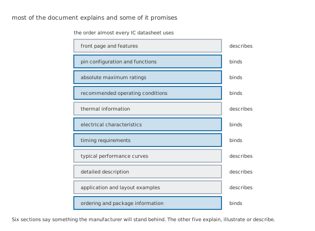
The order is close to universal. The split down the right-hand column is what the lesson is about.
Almost every IC datasheet lays itself out the same way, which is a real convenience once you notice it: you can find the section you want without reading the ones you do not.
The sections that bind are the ones with test conditions attached to every row. Absolute maximum ratings say what destroys the part. Recommended operating conditions say where it was designed to work. Electrical characteristics and timing requirements give the numbers, each with the supply, temperature and load they were measured under. The pin table says what each pin is. The ordering information says which variant you actually bought.
The sections that describe are everything else. The front page sells. The typical performance curves show a part, characterised carefully, that is not necessarily yours. The block diagram is a teaching aid, often simplified past the point of being a schematic. The application circuits are starting points, and their component values are illustrations unless the surrounding text says otherwise.
None of that middle section is filler and skipping it is a mistake. It is where you find out what the part is for, which the tables never tell you. It is just not what you quote in a worst-case calculation.
Engineer
Timing, which is the part a resistor never has
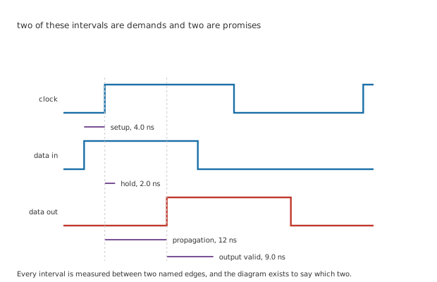
Two of the four intervals are what the part asks of you. Two are what it gives back.
A timing diagram looks like a waveform and is not one. It is a dimensioned drawing, and every interval on it is measured between two named edges. What matters is which direction each interval points.
An invented part runs through the rest of this lesson: 12 ns of typical propagation delay on a 3.3 V rail specified from 2.7 V to 3.6 V, with 4.0 ns of setup, 2.0 ns of hold and 9.0 ns of output-valid time. Every number is an invention and belongs to no catalogue part.
Setup and hold are demands. They say what the world must do for the part to work: the data has to be steady for 4.0 ns before the clock edge and stay put for 2.0 ns after it. Miss either and the part is entitled to give you anything at all.
Propagation and output-valid are promises. The output will change within 12 ns of the edge and will hold its answer for 9.0 ns.
Getting the direction wrong is the classic error, and it is easy, because both kinds sit in the same table in the same format.
The number the table never states
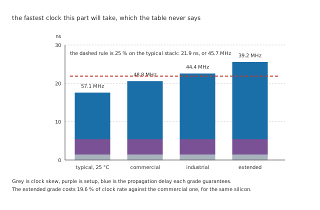
Grey is clock skew, purple is setup, blue is the delay each grade guarantees.
Nobody writes "maximum clock frequency" in a timing table, because it depends on what the part is connected to. It falls out of three numbers all the same.
Worked example — Adding up one clock period
Between one clock edge and the next, the signal has to leave this part, arrive somewhere, and be steady before that clock edge.
That is 12 ns of propagation, 4.0 ns of setup at the far end, and 1.5 ns of clock skew between the two: 17.5 ns in total, which is 57.1 MHz.
Allow 25 % for everything nobody counted and the period becomes 21.9 ns, or 45.7 MHz.
Both of those numbers were built on the typical delay, which is the trap. The typical column describes a population; it does not promise anything about the part you soldered down.
Professional
What the grade and the code decide
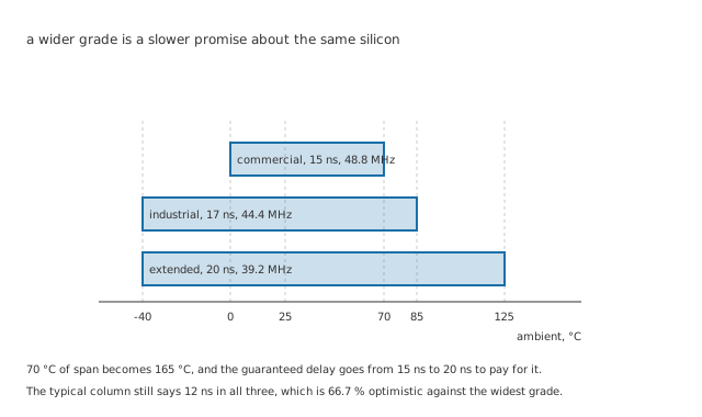
The wider the bar, the slower the promise. It is the same silicon in all three.
A part with one die is usually sold in several temperature grades, and the grades are not different parts. They are different promises about the same part, tested and binned differently.
Worked example — What the wider grade costs
The commercial grade covers 0 °C to 70 °C, a span of 70 °C, and guarantees 15 ns of delay — a ceiling of 48.8 MHz.
The industrial grade covers -40 °C to 85 °C, or 125 °C, at 17 ns and 44.4 MHz. The extended grade reaches 125 °C across 165 °C, at 20 ns and 39.2 MHz.
That is 19.6 % of clock rate given away for the temperature range, and the typical column still says 12 ns in every one of them — 66.7 % optimistic against the widest grade.
The ordering code carries three decisions the schematic never sees
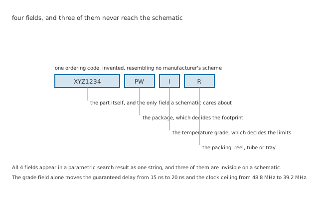
Three of the four fields are invisible on a schematic and all four are on the reel.
A schematic carries a part number. A purchase order carries a string, and the string has 4 fields in it.
The base number names the part. The next field names the package, which decides the footprint and whether the board can be assembled. One letter names the temperature grade, which decides the limits above. The last field names the packing, which decides whether a reel arrives when you wanted a tube of ten.
Only the first field is usually on the drawing, which is how a board gets built with the right silicon in the wrong package, or with a commercial-grade part in a design verified against industrial limits.
And what a guaranteed row is actually standing on
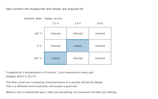
Two corners are measured on every part shipped. The other seven are argued for.
A row in an electrical characteristics table says a limit holds across a whole operating range. It cannot mean that every part was measured everywhere in that range, because measuring costs money and time and the range is continuous.
Worked example — How many corners get measured
Take 3 supply voltages, 2.7 V, 3.3 V and 3.6 V, against 3 temperatures: 9 corners.
Production test measures 2 of them on every part that ships, because a tester's time is the expensive part of the process.
That is 22.2 % measured and the rest inferred, from a characterised sample and from the design.
This is not a scandal and it is not a reason to distrust the number. It is how semiconductors are made, the characterisation behind those seven corners is usually thorough, and the guaranteed limit already includes the margin that inference demands. What it does mean is that where a datasheet labels a row as production tested rather than guaranteed by design, it is telling you something real. An unmarked row is not telling you the opposite; it is telling you nothing, and that is the difference worth noticing.
Reading one against a question
Arrive with a question. "Does it work at my supply", "does it hold accuracy at my temperature", "how fast can I clock it". A datasheet read cover to cover is a datasheet read badly.
Find the row, then read the conditions cell. The number without the conditions is not a number.
Check which column you are in. Minimum and maximum bind. Typical describes, and 66.7 % is how far apart the two can be.
Check the grade before you check anything else. The whole table is grade-dependent, and the grade is in the ordering code rather than in the title.
And when the document does not answer the question, ask. Interpolating between two rows of a table is inventing a specification, and the manufacturer's applications engineers exist precisely so that nobody has to.
Common mistakes
- Designing to the typical column — 12 ns typical becomes 20 ns guaranteed in the extended grade, which is 66.7 % more. A clock paced off the typical stack at 45.7 MHz is already too fast for two of the three grades.
- Reading setup and hold as promises — they are demands the part makes of your board. Propagation delay and output-valid time are the promises. All four sit in one table in one format.
- Ignoring the grade letter in the ordering code — it moves the guaranteed delay from 15 ns to 20 ns and the ceiling from 48.8 MHz to 39.2 MHz, on silicon that is otherwise identical.
- Quoting an application circuit's component values as specifications — that section describes rather than binds, and its values are illustrations unless the text says otherwise.
- Taking a curve as a limit — typical performance curves are characterisation of a sample. The tables are what is production tested or guaranteed, and only 22.2 % of the corners behind them are measured on every part shipped.
- Verifying against one revision and buying against another — limits, pin descriptions and occasionally pinouts move between datasheet revisions, and errata are a separate document that has to be asked for by name.
Frequently asked questions
If typical is not a promise, why is it in the table at all?
Because it is what the part will almost always do, and most decisions do not need a worst case. Estimating power consumption, sizing a decoupling capacitor or working out roughly how warm a board will run are all typical-column jobs. The distinction is not that typical is useless; it is that a limit calculation has to use a limit, and the two get mixed up because they sit in adjacent columns.
What does a blank cell in a min or max column mean?
That nothing is guaranteed there, which is not the same as unlimited. A parameter with only a maximum has no promised minimum, so a design that needs the parameter to be at least something has no support from that row. It is one of the commonest ways a datasheet declines to answer a question, and it usually means the answer is available from the manufacturer rather than from the document.
Can I use a part outside its temperature grade if I keep it cool?
If you keep it inside the grade's range, that is exactly what the grade is for. Running a commercial part at 85 °C is a different matter: nothing in the datasheet covers it, the part will very likely work, and there is no specification to appeal to when it does not. For one prototype that is a reasonable risk. For anything shipping, the grade is the cheapest insurance in the design.
Why does a timing table sometimes give a minimum propagation delay?
Because a fast part can be a problem too. If an output changes too soon after a clock edge it can violate the hold requirement of whatever is receiving it, and no amount of slowing the clock fixes that — hold violations are independent of frequency. A minimum propagation delay is the manufacturer promising the output will not move before a stated time, which is what makes that hold arithmetic possible.
Where does the clock skew number come from?
Not from the datasheet. It is a property of your board: the difference in arrival time of one clock edge at two places, set by trace lengths, by the buffer that drives them and by loading. The 1.5 ns used here is an invented allowance. On a small board it is often smaller; on a large one with a clock tree it can dominate everything else in the budget.